
Jaw pad cover

Inactive Publication Date: 2010-11-30
FINK JOSHUA M +1
View PDF8 Cites 36 Cited by
  • Summary
  • Abstract
  • Description
  • Claims
  • Application Information

AI Technical Summary

Benefits of technology

[0010]It is therefore an object of this invention to provide a jaw pad cover which avoids the aforementioned problems of prior art jaw pads.

Problems solved by technology

The problem with such jaw pads is that, when in contact with a jaw of a user, they are uncomfortable, cold to the touch during cold weather and can slide when subjected to perspiration or when jostled and can thereby interfere with the desired operation during, for example, a football game when they can cause the helmet to slip, which may cause an undesirable equipment malfunction type of injury.
Another problem with typical jaw pads is that they can cause skin irritations such as chaffing or a rash and are not suitable for receiving the application of anti-microbial topical products such as Microban™ thereupon.
Also, the white or creme colored outer casing of the jaw pad is non aesthetically pleasing; it shows dirt and grass stains, is difficult to clean and is not lauderable.
It is also costly and time consuming to replace a jaw pad.
Furthermore, due to sanitary reasons, the typical jaw pads are unusable by other team members.

Method used


Image

  • Jaw pad cover
  • Jaw pad cover
  • Jaw pad cover

Examples


example 1

[0044]A prototype of the jaw pad cover 10 was constructed from readily available materials and was successfully tested.

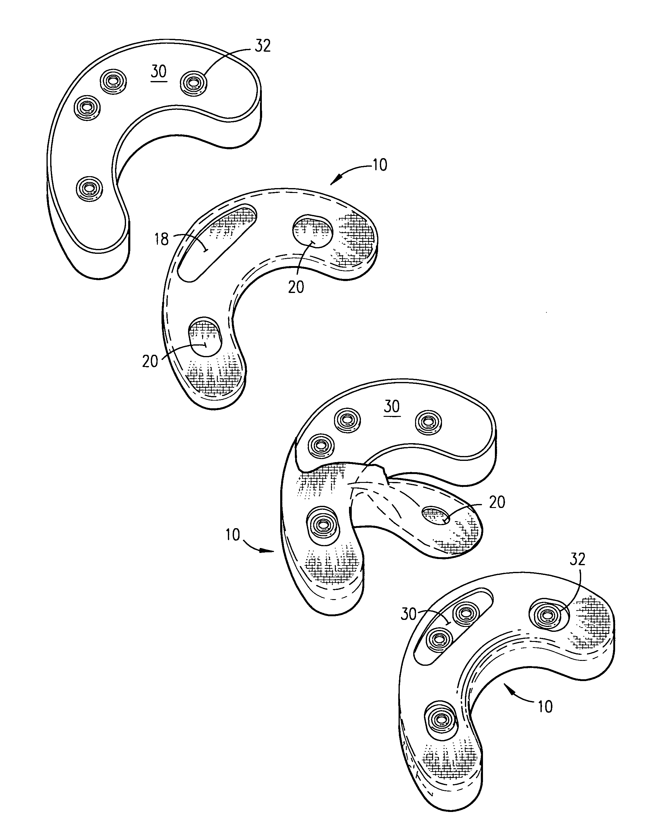
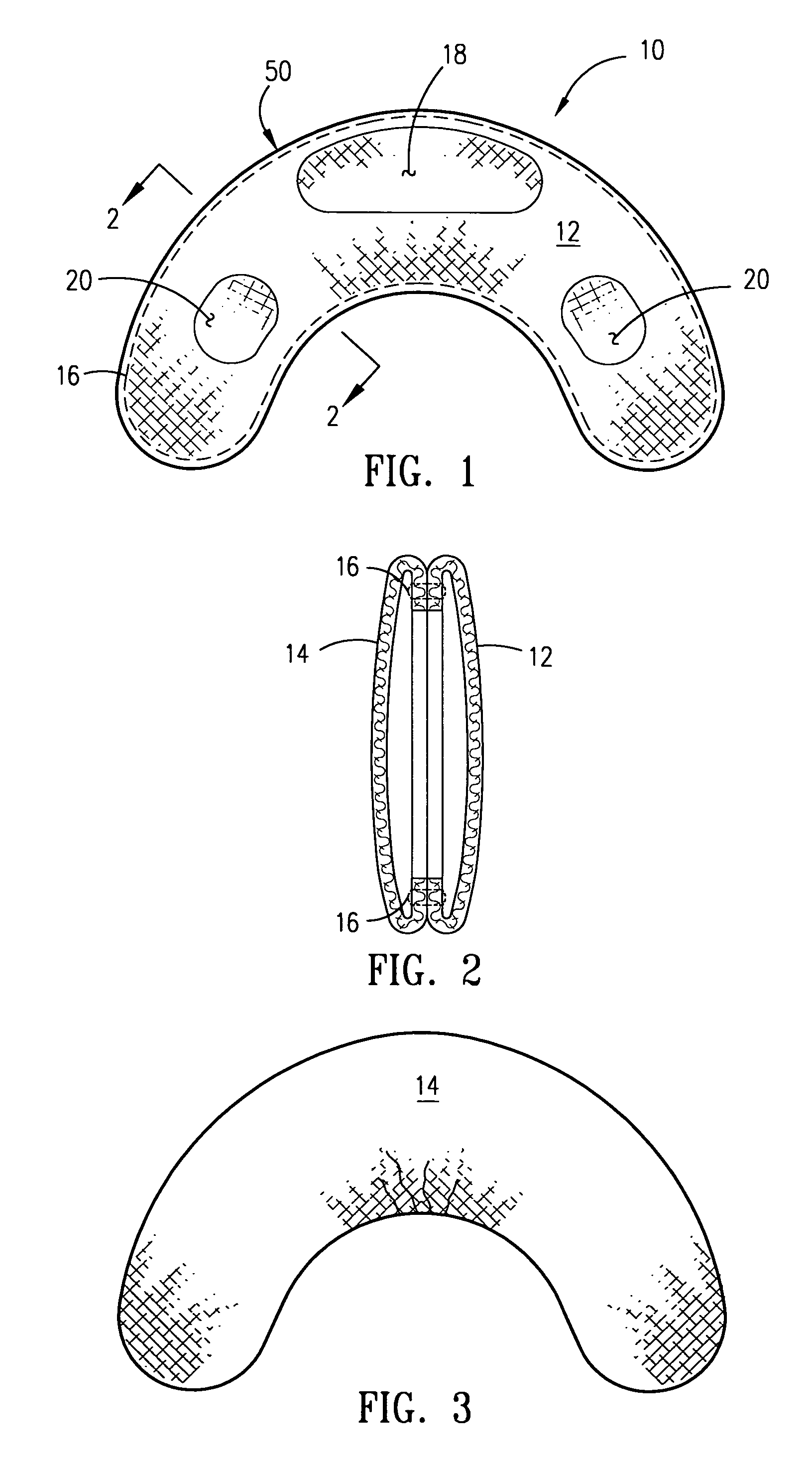
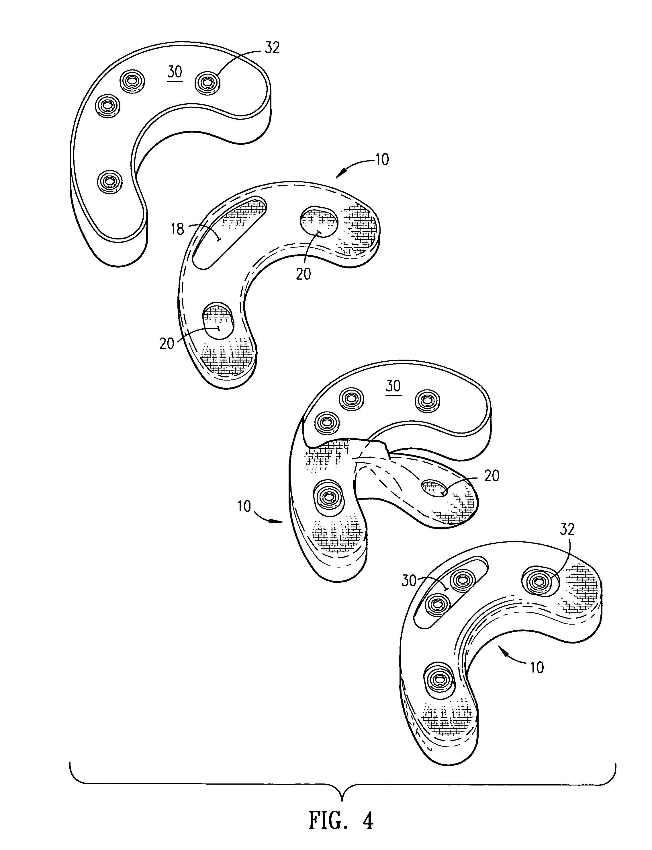
[0045]In this illustrative example, the jaw pad cover 10 was made from a material blank 50 with the first section 12 made of a rubberized fabric material capable of being die cut and the second section 14 was fabricated from Spandex® and joined together by a stitch 16. Being readily available, the material blank 50 was black in color. The first section 12 had a close woven rubberized fabric material and the second section 14 had a herring bone pattern. The jaw pad cover 10 was dimensioned to correspond to fit a jaw pad 30 having a crescent shape with a size of about 4 inches (10.2 cm) long by 1¼ inches (3.2 cm) wide by 1 inch thick (2.5 cm) with the fastening means 32 comprising four female snap members for matingly mounting thereon the headgear 40 via corresponding male snap members (not shown). The first section 12 has a first aperture 18 and a second aperture 20 ...

example 2

[0051]A second prototype of the jaw pad cover 10A was constructed from readily available materials and was successfully tested.

[0052]In this second illustrative example, the jaw pad cover 10A was made from a material blank 50A with the first section 12A and the second section 14A fabricated from Spandex® and joined together by a stitch 16A. Being readily available, the material blank 50A was red in color. The jaw pad cover 10A was dimensioned and generally constructed to correspond to fit the jaw pad 30 in a manner as in EXAMPLE 1. The first aperture 18A being larger than the second aperture 20A to allow the jaw pad 30 to freely pass therethrough and the fastening means 32 on the jaw pad 30 being visible and accessible for mounting on the headgear 40. The first aperture 18A has the stitch 16A disposed in a saw tooth pattern and a second aperture 20A with a sewn reinforcement 22 thereabout. The completed jaw pad cover 10A was stretched over the jaw pad 30 and was found to cover the j...


PUM


Abstract

A jaw pad cover for expandably conforming to a shape of a jaw pad for protectively covering the jaw pad of a headgear is provided. The jaw pad cover comprises a stretchable material blank having a first section and a second section joined together with a stitch. The means for receiving the jaw pad therein the jaw pad cover is therethrough a first aperture and a second aperture therein the first section. The first aperture is larger than the second aperture to allow the jaw pad to freely pass therethrough so that when the jaw pad is positioned therein the jaw pad cover, a fastening means on the jaw pad for receiving the jaw pad and the jaw pad cover on the headgear is accessible therethrough the second aperture.

Description

FIELD OF THE INVENTION[0001]This invention relates generally to a cover for a jaw pad. More particularly, the present invention relates to a stretchable jaw pad cover for protectively covering a jaw pad of a headgear.BACKGROUND OF THE INVENTION[0002]Jaw pads are used on headgear particularly on football helmets to protect the jaw of a user from shock caused by impact from a blow to the body such as from a tackle or from a block during a football game. It is noted that although the discussion herein, for clarity, illustratively mentions football helmets, it is understood that other types of headgear such as those worn by fighters when boxing, wrestlers, bicycle and motorcycle riders, automobile racing drivers, soccer players, hockey players, lacrosse players, baseball players, firefighters, military personnel and any other types of headgear where a jaw pad is supplied will encompass the intent and meaning of this disclosure without departing therefrom.[0003]The typical protective hel...

Claims


Application Information

Patent Timeline
IPC IPC(8): A42B3/00A63B71/10
CPCA42B3/127A63B71/10A63B2243/0066
Inventor FINK, JOSHUA M.STOREY, ROBBIE M.
Owner FINK JOSHUA M
Learn More