Package pick-off and delivery device

a technology for packaging and delivery devices, applied in the field of packaging, can solve the problems of loss of vacuum pressure or suction in the entire vacuum system, increasing the difficulty of manufacturers to use suitable transfer mechanisms to enable, and failure of subsequent transfer and placement processes

Active Publication Date: 2010-11-30
BEMIS COMPANY INC
View PDF6 Cites 15 Cited by
  • Summary
  • Abstract
  • Description
  • Claims
  • Application Information

AI Technical Summary

Problems solved by technology

However, due to the many configurations, shapes, and sizes of packaged articles required to be transferred and processed, it has become increasingly difficult for manufacturers to use suitable transfer mechanisms which enable the reliable pickup, transfer, and placement of these articles.
For example, during the transfer of a packaged product, engagement with the package may be incomplete, thus, causing a failure in the subsequent transfer and placement processes.
Generally, this type of malfunction results from a loss of vacuum pressure or suction in the entire vacuum system.
However, because suction cups are often of a lightweight and rather pliable material, e.g., rubber, and the surface of an article can be textured or irregular, gaps may exist between the suction cup and the article which allows ambient atmosphere to leak into the suction cup cavity.
Leakage of air into the suction cup cavity depletes the internal vacuum pressure and consequently, limits the lifting force that can be generated.
Typically, the leakage of one suction cup affects the vacuum pressure in an entire system, leaving other suction cups without adequate suction and lifting force.
Leakage is particularly a problem with irregularly shaped products packaged in flexible packaging materials which has a greater tendency to have textured and uneven surfaces.
Loss of vacuum pressure can also occur when there is internal structural damage to vacuum system components due to repetitive high speed motion of the rotary transfer device.
Typically, these components include one or more metallic solder joints, and over time, the solder cracks due to metal fatigue and subsequently, air leaks into the component and results in the loss of vacuum pressure.

Method used


Image

  • Package pick-off and delivery device
  • Package pick-off and delivery device
  • Package pick-off and delivery device

Examples


Embodiment Construction

[0016]Reference will now be made in detail to exemplary embodiments of the present invention which are illustrated in the accompanying drawings. Whenever possible, the same reference numbers will be used throughout the drawings to refer to the same or like parts.

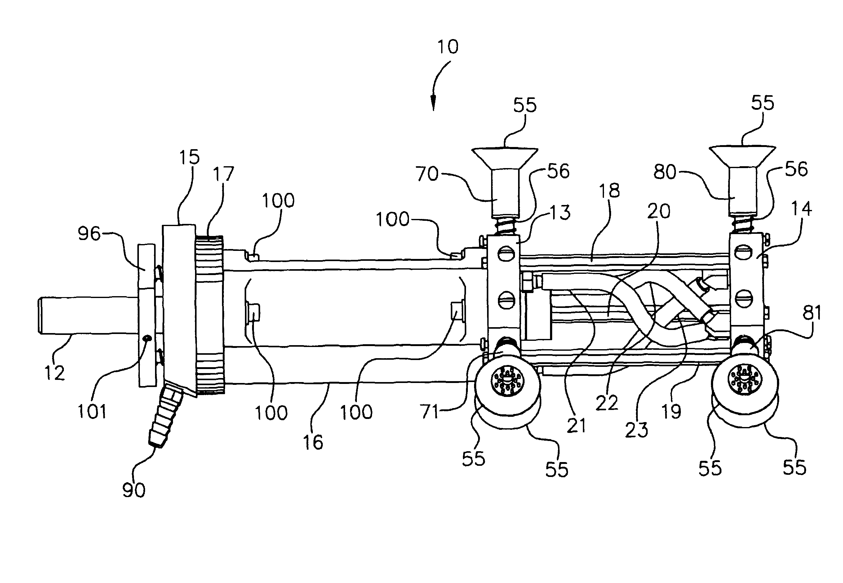
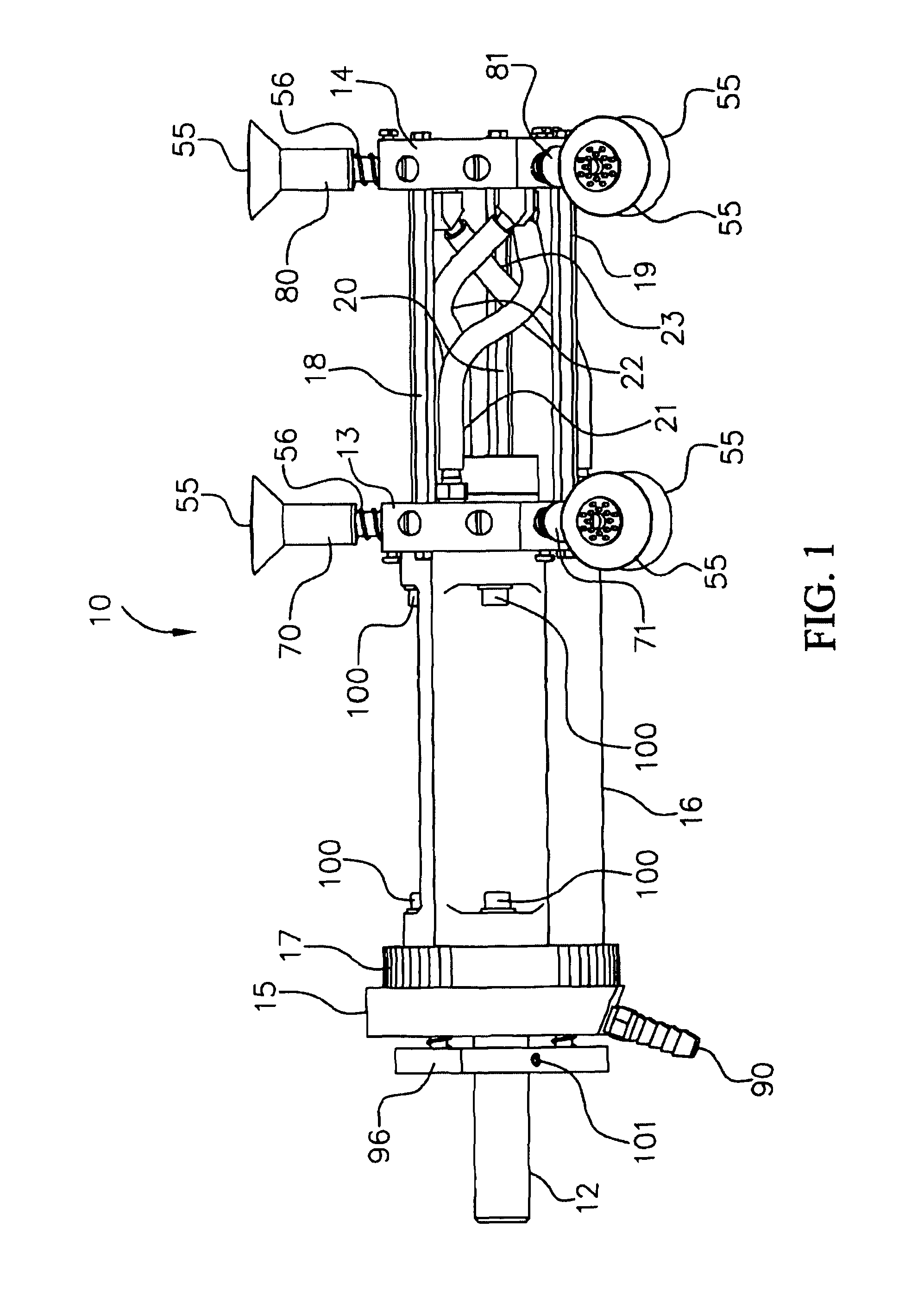
[0017]FIGS. 1 and 4 depict one embodiment of the article-handling device 10 for use in packaging machines in accordance with the present invention. Article-handling device 10 is shown as having a longitudinal stationary support shaft 12. The support shaft 12 is generally of a metal construction having a central axis, denoted as A-A. Support shaft 12 may be held stationary to a frame structure (not shown) of the packaging machine so as to not rotate. Although not shown in the drawings, the frame structure can be constructed in a variety of configurations for installation in conjunction with a variety of mechanized operations associated with packaging equipment and packaging machines. In one embodiment, the configuration may i...


PUM


Abstract

A article-handling device includes a means of rotation, a vacuum conduit, and a first vacuum manifold, each rotatably mounted onto a stationary support shaft. The device further includes a second vacuum manifold affixed to the first vacuum manifold and a non-rotatable control valve which is operational synchronized with the rotation means to provide both vacuum pressure and atmospheric pressure independently to each of the first and second vacuum manifolds. Each of the vacuum manifolds comprises one or more tubular suction shafts each having a suction cup affixed thereto. The suction shafts of each vacuum manifold are spatially arranged such that at least a first suction shaft of the first vacuum manifold is substantially parallel to a first suction shaft of the second vacuum manifold thereby enabling the suction shafts to function as a paired unit. In this way, at least the first suction shaft of said first vacuum manifold and the first suction shaft of said second vacuum manifold are each independently adapted to attract and hold said article when the first and second vacuum manifolds are operationally connected with said vacuum pressure and release said article when the first and second vacuum manifolds are operationally connected with said atmosphere pressure.

Description

TECHNICAL FIELD[0001]This invention relates to an article-handling apparatus suitable for use with packaging machines and, more particularly, to an apparatus for transferring flexible packages from and to a plurality of predetermined locations.BACKGROUND OF THE INVENTION[0002]It has become increasingly necessary and desirable in packaging operations to enable the pick-up, transfer and delivery of packaged articles of various shapes and dimensions in the most reliable, precise and high-speed manner. Many types of such devices have been developed, including the utilization of rotary transfer devices having a vacuum system. Generally, the rotary transfer device functions in cooperation with a vacuum source to pickup, hold and place the packaged product during transfer. Typically, vacuum suction cups of the rotary transfer device engage an article at a predetermined location and for a predetermined period, and then, disengage the article after transfer from one location to another. Howe...

Claims


Application Information

Patent Timeline
Patent Type & Authority Patents(United States)
IPC IPC(8): B25J15/06
CPCB65B61/28B65G47/848B65B31/028
Inventor NANKERVIS, WAYNE THOMASNOWAK, KENNETH EUGENEWEGNER, PAUL EDWARD
Owner BEMIS COMPANY INC
Why Eureka
Try Eureka