Multiple material piping component

a technology of piping components and materials, applied in the direction of instruments, liquid/fluent solid measurement, volume/mass flow by differential pressure, etc., can solve problems such as not being economically performed, and achieve the effect of low cos

Inactive Publication Date: 2010-12-07
SAVANT MEASUREMENT CORP
View PDF256 Cites 64 Cited by
  • Summary
  • Abstract
  • Description
  • Claims
  • Application Information

AI Technical Summary

Benefits of technology

[0017]In view of the described opportunities for improvement in the oil, gas, petroleum and chemical industries, this invention provides low cost piping components that comply with DOT regulations and ASME standards, as well as withstand the hostile fluid environment of the oil, gas, petroleum and chemical industries.
[0019]The piping component body is comprised of non-steel, or a combination of steel and non-steel parts. Ideally, the body is comprised of plastic, which is less expensive and facilitates forming, including machining or molding while maintaining its structural integrity in a hostile fluid environment, such as in oil, gas, petroleum or chemicals. Alternatively, ceramic could be used to fabricate the body.
[0020]Because plastic is easily formed, the bodies of various piping components can be formed in new and different shapes that previously could not be economically performed due to the limitations of working with metal. For example, the upstream and / or downstream sides of the bodies of plastic flow conditioners can be formed into concave or convex profiles with or without steps. It is contemplated that many piping component bodies will be able to take on different shapes and configurations than the current standard designs, because plastic can be formed easier and at a reduced cost.

Problems solved by technology

Because plastic is easily formed, the bodies of various piping components can be formed in new and different shapes that previously could not be economically performed due to the limitations of working with metal.

Method used


Image

  • Multiple material piping component
  • Multiple material piping component
  • Multiple material piping component

Examples


Embodiment Construction

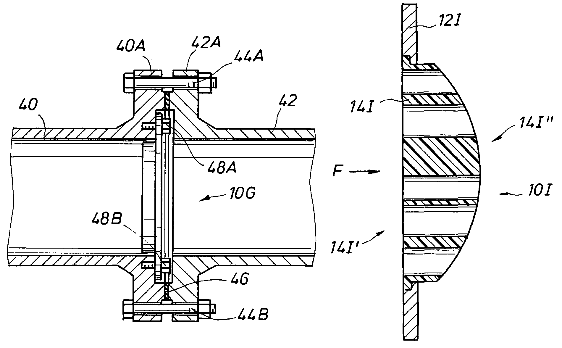
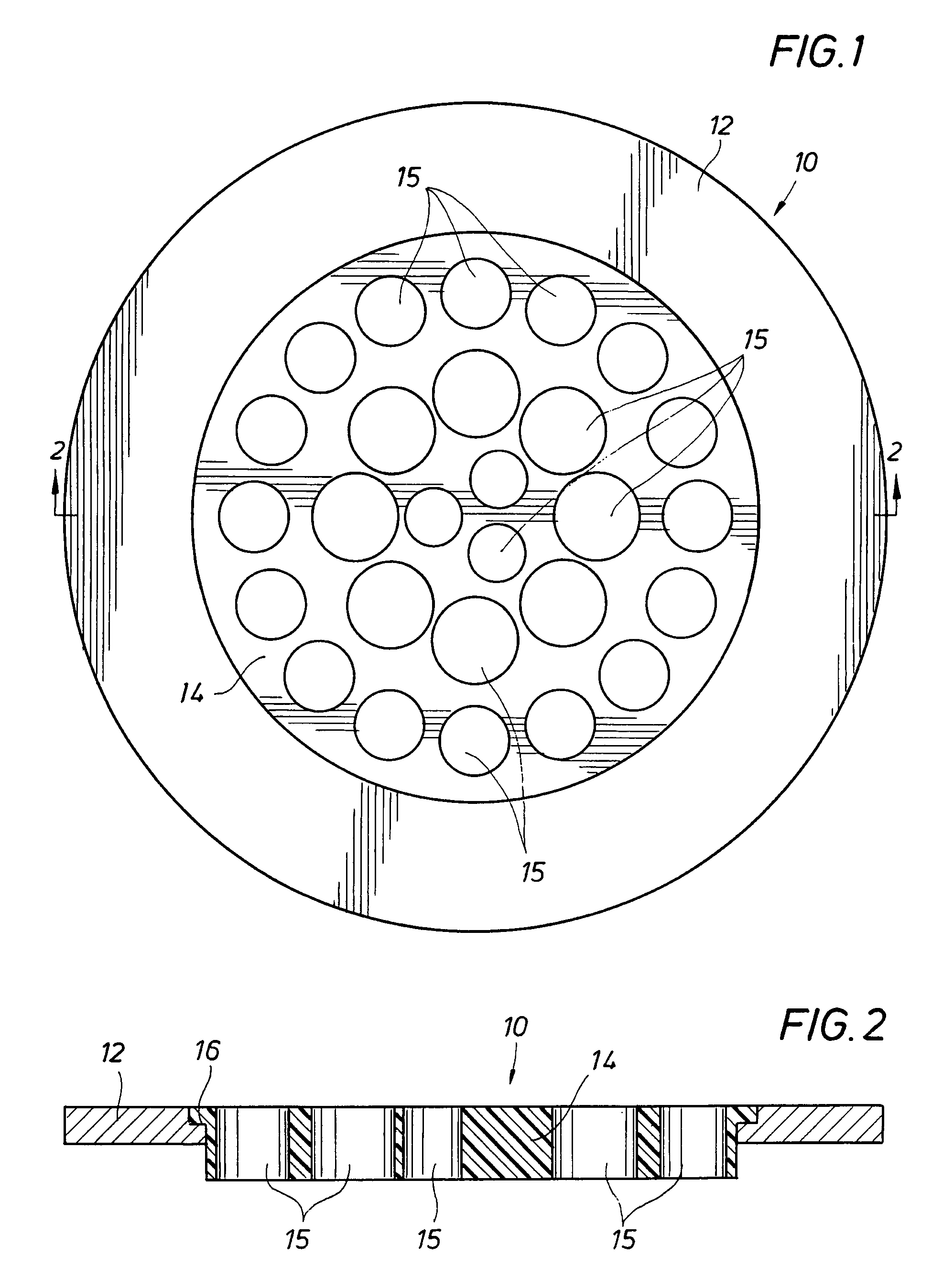
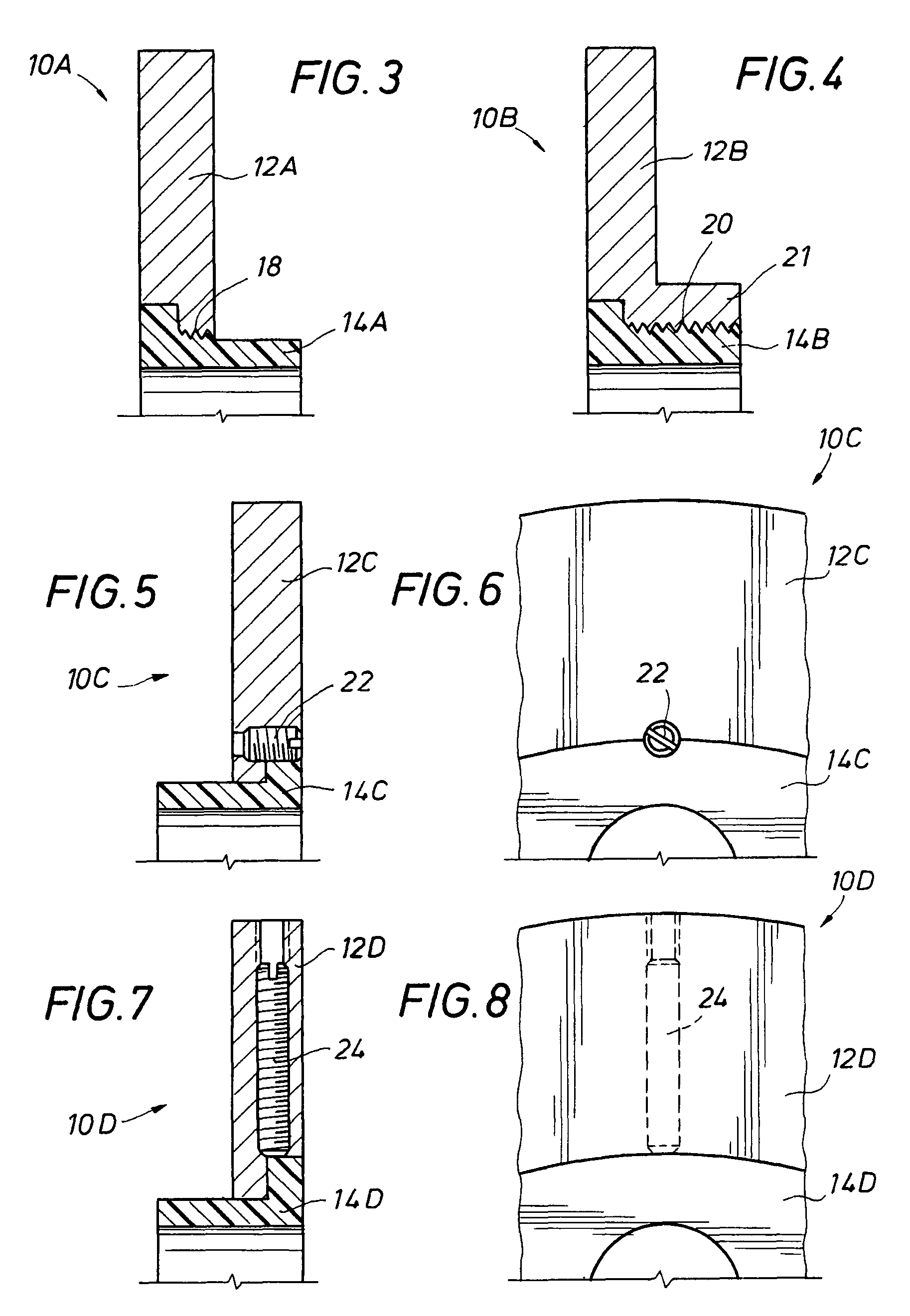
[0068]Generally, the present invention provides a low cost piping component that complies with DOT regulations and ASME standards, as well as withstands the hostile fluid environment in the piping systems of the oil, gas, petroleum and chemical industries along with a method for manufacturing the piping component.

[0069]The piping component according to the present invention is comprised in part of a metal, such as steel, to fabricate a housing to be positioned with steel piping. The steel housing forms an opening in which the piping component body is positioned. The piping component body could be fabricated from plastic or ceramic or a combination of plastic or ceramic and metal. The plastic and ceramic should have properties that are compatible with the hostile oil, gas, petroleum and chemical environments. An exemplary ceramic for use in these environments is partially stabilized zirconia sold under the trademark NILCRA by ICI Australia Operations Proprietary Limited of Melbourne,...


PUM


Abstract

The piping component is comprised in part of a metal housing that is positionable with a metal pipe. The metal housing forms an opening in which a piping component body is inserted. The body of the piping component can be fastened to the metal housing using an epoxy adhesive, a set screw connection, a threaded connection, press fit connection, a key connection or a pin connection or a combination of these connections. The body is comprised of plastic, which is less expensive than metal and facilitates forming, including machining or molding, while maintaining its structural integrity in a hostile fluid environment, such as in oil or gas. Piping components such as flowmeters, flow conditioners, small volume provers, static mixers, samplers, and valves are contemplated for use with these multiple materials.

Description

CROSS-REFERENCE TO RELATED APPLICATIONS[0001]N / ASTATEMENT REGARDING FEDERALLY SPONSORED RESEARCH OR DEVELOPMENT[0002]N / ANAMES OF THE PARTIES TO A JOINT RESEARCH AGREEMENT[0003]N / AREFERENCE TO SEQUENCE LISTING[0004]N / ABACKGROUND OF THE INVENTION[0005]1. Field of the Invention[0006]The present invention relates to piping components for use with fluids in pipes. Particularly, this invention relates to piping components for use with fluids in piping in the oil, gas, petroleum and chemical industries.[0007]2. Description of the Related Art[0008]Piping used in the oil gas, petroleum and chemical industries are regulated in part by the Department of Transportation (“DOT”). In addition, the American Society of Mechanical Engineers (“ASME”) provides standards associated with oil and gas facilities.[0009]For example, pipes carrying hazardous liquids such as hydrocarbons are regulated by DOT Title 49 C.F.R. §195. This regulation states that piping and all associated connections be comprised of...

Claims


Application Information

Patent Timeline
Patent Type & Authority Patents(United States)
IPC IPC(8): F15D1/04
CPCF16L9/147F16L9/19F16L39/00
Inventor GALLAGHER, JAMES E.GALLAGHER, MICHAEL D.
Owner SAVANT MEASUREMENT CORP
Why Eureka
Try Eureka