
Bed formed from face to face chairs

Active Publication Date: 2010-12-07
JETBED INC
View PDF19 Cites 20 Cited by
  • Summary
  • Abstract
  • Description
  • Claims
  • Application Information

AI Technical Summary

Benefits of technology

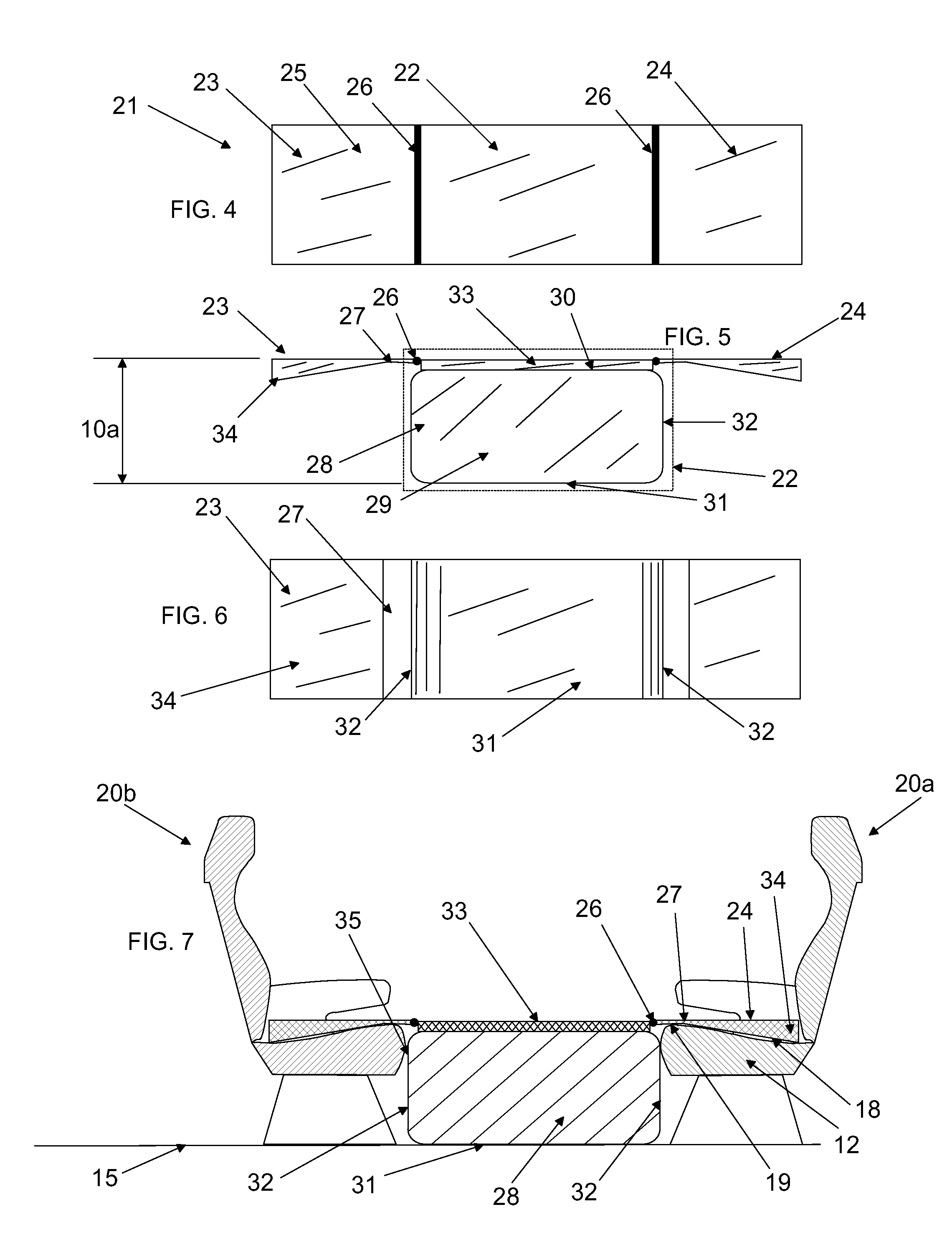
[0014]In one form of the invention bed device, the above discontinuities and seat declinations are eliminated. A top pad, preferably enclosed in a soft but durable fabric envelope, is attached to the entire top surface of the foundation block, forming a relatively planar first bed surface parallel to the floor. Adjacent edges of the top pad lie substantial adjacent to a upper elevation of the seat cushions of each seat, i.e., at a front edge of the seat cushion. Connected by hinges or flexible hinge-like attachment to the adjacent edges are connection edges of filler pads. Filler pads are adapted to lie on the top surface of a declination type seat and substantially conform, on a underside, to the declination curvature. A second bed surface of the filler pads is a flat topside and substantially co-planar with the first bed surface. The entire bed surface upon which a user may lie on their back, side or stomach consists of a first bed surface of the top pad and two second bed surfaces of the filler pads adjacent to and substantially co-planar with the top pad. The flexible or hinge connection between the top pad and the filler pads eliminates sensed discontinuities in the entire bed surface.
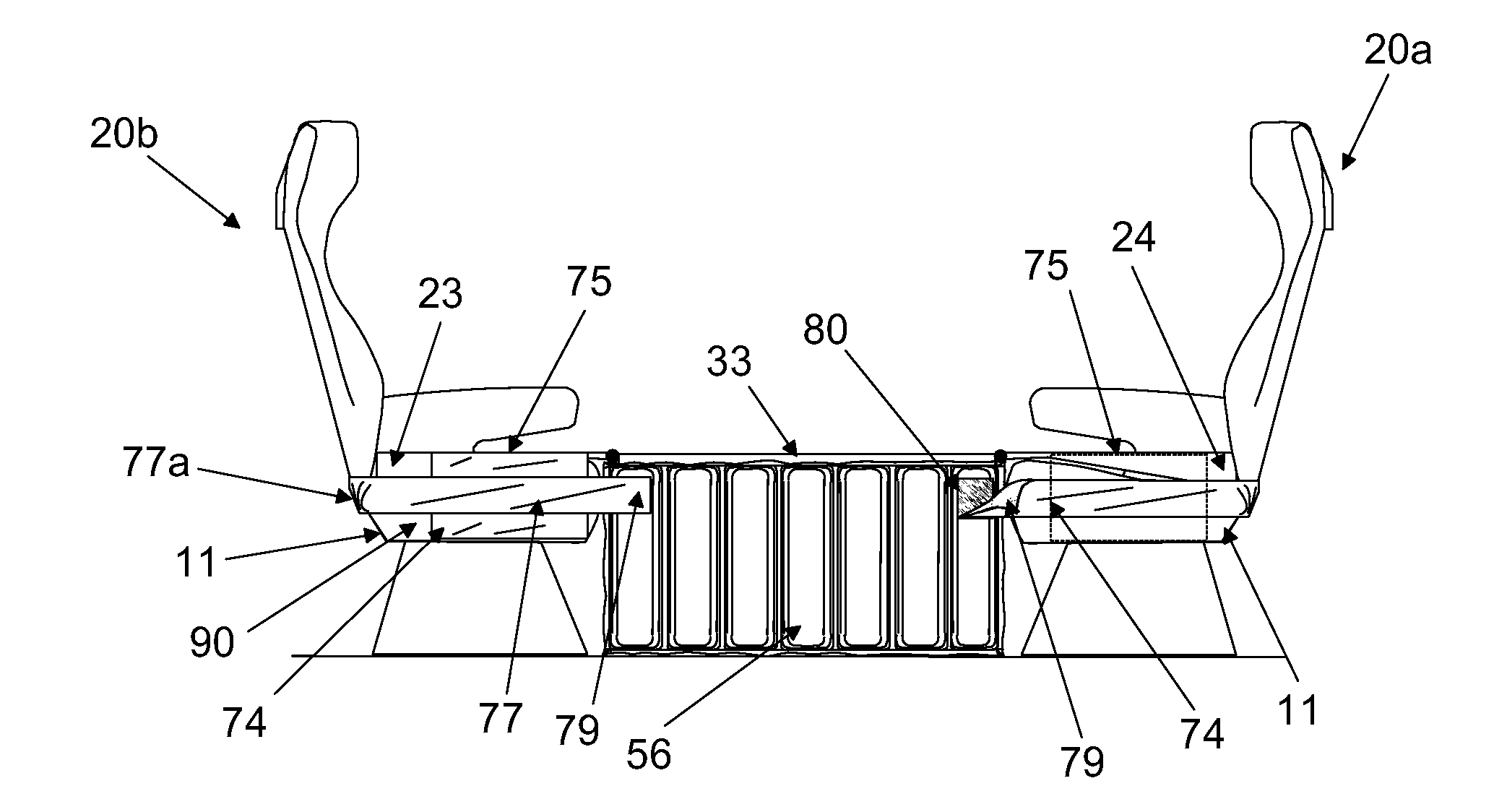
[0016]A further embodiment of securing means comprises a lateral extension from a side of one or both of the filler pads. The lateral extension is flexibly attached to the side of the filler pad and is adapted to fold down from the side of the filler pad and to be secured to a side of the seat below the level of the top of the seat cushion. Securing the lateral extension to the side of the seat can be accomplished by overlaying it with a flexible belt extending from sidewalls of the foundation block and around the sides and back of the seat structure. Alternately, the lateral extension can be secured to an adjacent surface of a right or left side of the seat by hook and loop fastening means, latches, snaps, or similar devices. It is preferred to arrange placement of the lateral extension on a side of the filler pad so that the lateral extension will lie on a side of the seat without an armrest and / or on a side nearest to a aircraft cabin wall. The lateral extensions, when secured to the right or left side of a seat, dramatically reduces movement of the foundation block relative to the seats. The lateral extension structurally connects a right or left side of the filler pad with the lower frame of the seat, where the filler pad is connected with the top pad and the top pad is fixed to a top surface of the foundation block. Using the lateral extensions in combination with securing means for the foundation block, it is unnecessary to fix the bottom of the foundation block to the floor in order to obtain a structure sufficiently secure to support the weight of a user and thereafter remain in location between the two facing seats. Undue side to side shifting of the foundation block is essentially eliminated.
[0020]3. to provide securing flanges or lateral extensions that extend from a lateral edge of the filler pads and down against a right or left side of a seat to reduce side to side movement of the entire assembly when in place;
[0022]5. to provide a fabric covered, foam top cushion for the foundation block top surface that is effectively continuous with the tops of the two filler pads so that a user experiences a uniform softness of the bed surface from one end to the other.
[0023]A user can lie down securely, with or without a straps about their body, for long periods of time on the bed surface. The foundation block can be deflated and other extensions from it folded into a small volume for compact storage.

Problems solved by technology

However, three features of this simplest example are undesirable.
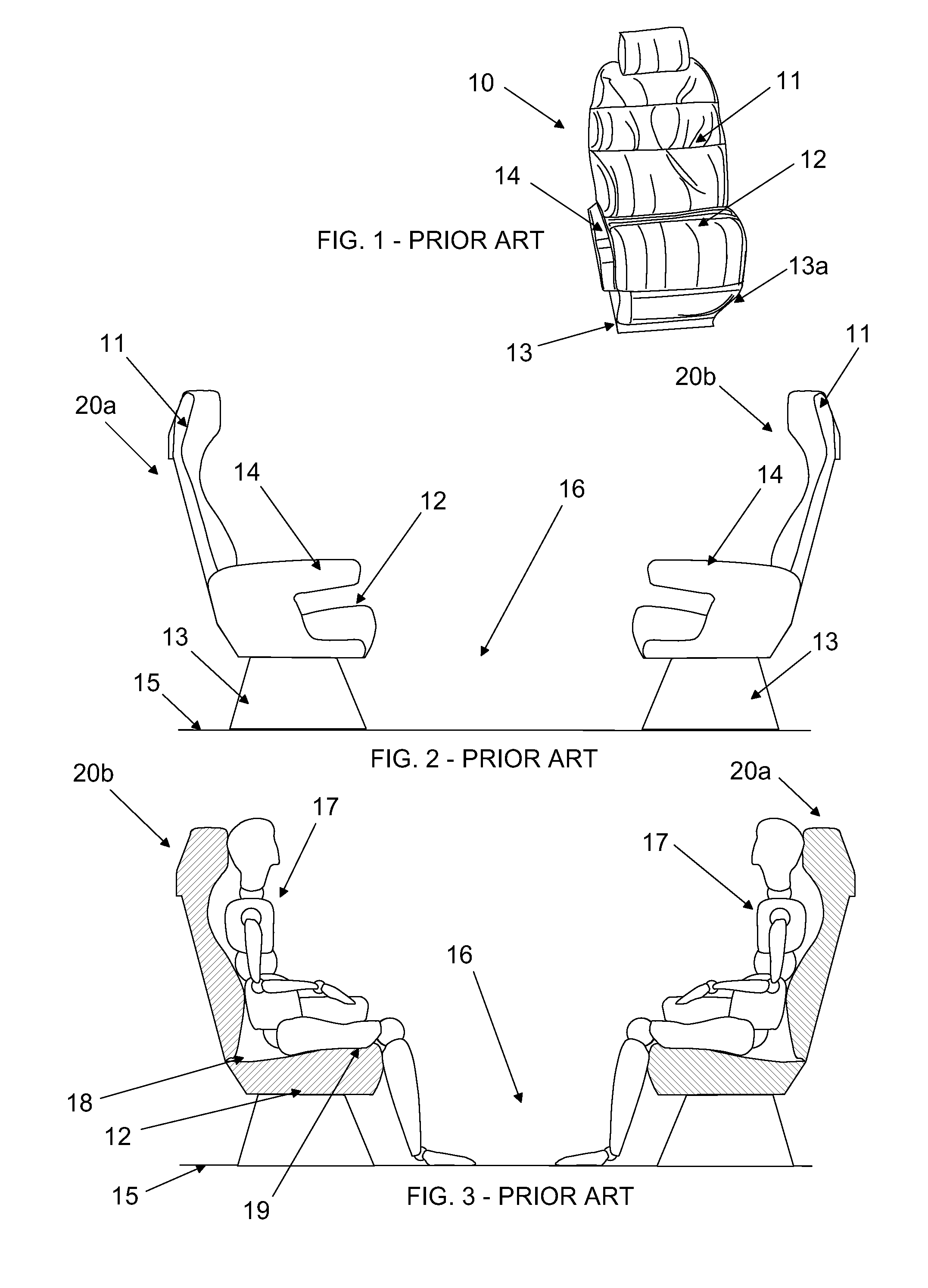
First, the foundation block is not fixed in place relative to the floor and the seats, allowing the foundation block to shift and perhaps become dislodged when a user lies on it.
Aircraft travel sometimes includes turbulent conditions or a user may shift their weight from side to side, either of which could cause the foundation block to be ejected from under a user.
Second, a user will perceive the breaks in continuity, material and cushioning perception between the top surfaces of the seats and the top surface of the foundation block.
These breaks and changes are ultimately a cause of discomfort over a long period of rest upon them.

Method used


Image

  • Bed formed from face to face chairs
  • Bed formed from face to face chairs
  • Bed formed from face to face chairs

Examples


embodiment 21

[0048]FIGS. 4, 5, and 6 are, respectively, top, side and bottom views of one embodiment 21 of center section 22 comprising a foundation block 28 and a top pad 33 attached to cover a top surface 30 of the foundation block 28. Foundation block 28 comprises a top surface 30, a bottom surface 31, end walls 32 and side walls 29. Filler pads 23 and 24 are connected by a rotatable connection 26 to a top edge zone of center section 22, where filler pads 23 and 24 are rotatable about an axis formed by connection 26. Connection 26 preferably comprises a connection of fabric covering filler pads 23 and 24 to fabric covering top pad 33. Filler pads 23 and 24 each comprise a thickened back section 34 and a thinner front edge section 27. Filler pads 23 and 24 are about a width of seat cushions upon which they will be supported. Top pad 33 is about the width of the filler pads 23 and 24. Elevation 10a is a height from the bottom surface 31 of foundation block 28 to a substantially co-planar set of...

embodiment 100

[0054]FIG. 16 is the invention embodiment 100 having the center section 22 and filler pads 23 and 24 of FIG. 4 with the addition to two lateral extensions 74 and two flexible belts 77 for securing a center section 22 to the seats shown in FIGS. 2 and 3. Lateral extensions 74 are connected by flexible, rotatable connection 75 to a side edges of filler pads 23 and 24. Flexible belts 77 are connected at a connection end 78 to side wall 22a of center section 22. Belts 77 are adapted to extend around right and left sides and back sides of facing seats to which the invention assembly 100 will be engaged to form a bed surface, where a releasable attachment ends 79 are adapted to be fixed to attachment sections 80 shown on side wall 22a of center section 22. FIG. 17 is a top perspective view of a portion of the foundation block 53 of FIGS. 11, 12 and 13 showing an connection end 78 connected with layers 63 at stitching 82 and with belt 77 at stitching 83 and attachment section 80 on side wa...


PUM


Abstract

The present invention is a device which quickly and inexpensively transforms two, face to face aircraft passenger seats into a horizontal bed surface adapted to provide a user with a flat surface upon which a user may lie on their back, side or stomach. A collapsible foundation block is adapted to form a space filling function as to a space between two face to face seats that are secured to a floor structure forming a horizontal surface. The foundation block is preferably inflatable and is supported from a floor surface between the two face to face seats, whereafter a supporting structure of the foundation block rises to a top surface generally parallel to the floor. The elevation of the top surface is approximately a level of a top surface of seat cushions of the two facing seats.

Description

FIELD OF THE INVENTION[0001]The present invention relates to bed structures having an inflatable or collapsible component.BACKGROUND OF THE INVENTION[0002]Aircraft seating for passengers is most efficiently laid out with all passengers seated side by side, with all passenger seats facing forward. A typical aircraft passenger seat comprises a set of supports anchored to a cabin floor, whereupon is secured a seat bottom securing a seat cushion. The seat cushion is a critical aspect of passenger orientation on the seat itself. The top surface of the seat cushion declines rearward from a front edge to a back edge of the seat cushion so that a passenger is urged against a curved seat back when seated. The change in elevation may be slight (such as about one inch change in elevation for coach seats) or may be very accentuated (2-4 inches for executive or first class seats). Seat declination in aircraft passenger seating serves a safety function, in that a passenger is less likely to be ej...

Claims


Application Information

Patent Timeline
IPC IPC(8): A47C13/00
CPCB60N2/345B64D11/06B64D11/0647B64D11/0641B64D11/0601
Inventor BOSSTICK, GERALD
Owner JETBED INC
Learn More