Supercharge Your Innovation With Domain-Expert AI Agents!

BLDC motor assembly

a motor assembly and brushless technology, applied in the direction of machines/engines, liquid fuel feeders, magnetic circuit shapes/forms/construction, etc., can solve the problems of motor damage, assembly time, expense and complexity of motor assembly, etc., and achieve the effect of reliable and inexpensive form of rotor assembly

Active Publication Date: 2010-12-07
CARTER FUEL SYST
View PDF122 Cites 13 Cited by
  • Summary
  • Abstract
  • Description
  • Claims
  • Application Information

AI Technical Summary

Benefits of technology

"The invention is a method for attaching permanent magnet segments into an operative array on a rotor for a brushless direct current (BLDC) electric motor assembly. The method involves supporting the magnet segments on the outer surface of the hub using an annular ring that is deformed in an electromagnetic forming operation to hold the magnet segments tightly against the hub. The invention provides a reliable, inexpensive, and efficient way to securely attach magnet segments to a rotor for a BLDC electric motor assembly. The motor assembly made in accordance with the invention overcomes the shortcomings and disadvantages of prior art attempts to securely, reliably, and inexpensively form a rotor assembly for a BLDC electric motor."

Problems solved by technology

This catastrophic failure of magnet separation from the underlying hub surface can lead to motor damage.
However, a shell of this type adds undesirable weight, expense and complexity to the motor assembly.
Again, a technique such as this contributes substantially to the manufacturing assembly time, and provides additional failure modes for the motor assembly, as well as adding substantially to the component complexities.

Method used


Image

  • BLDC motor assembly
  • BLDC motor assembly
  • BLDC motor assembly

Examples


Embodiment Construction

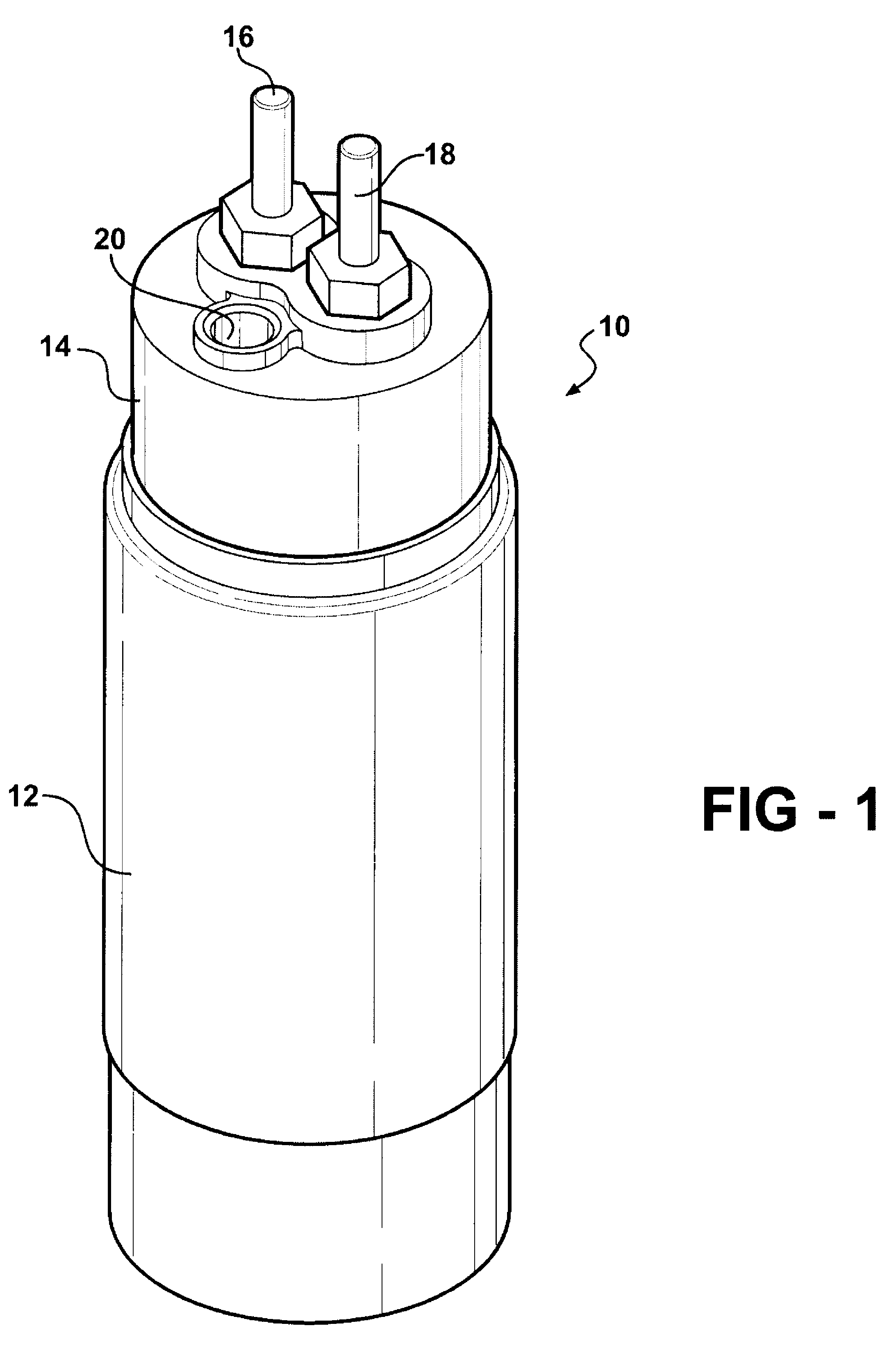
[0025]Referring to the Figures, wherein like numerals indicate like or corresponding parts throughout the several views, in a liquid fuel pump is generally shown at 10 in FIG. 1. The fuel pump 10 is of the type used in vehicular applications for fuel that is transferred from a storage tank to an internal combustion engine. However, the pump 10 may be used for other purposes than transferring fuel, and indeed the novel aspects of the invention as relating to the BLDC motor assembly can be used fully apart from and without any reference to the fuel pump 10 or any pump assembly per say. The fuel pump 10 is shown including a sleeve-like housing 12 having a generally cylindrical configuration. An outlet cap 14 encloses the upper end of the housing 12 and provides an interface for electrical connections via terminals 16, 18 as well as a fuel outlet port 20 into which a fuel delivery coupling (not shown) can be attached.

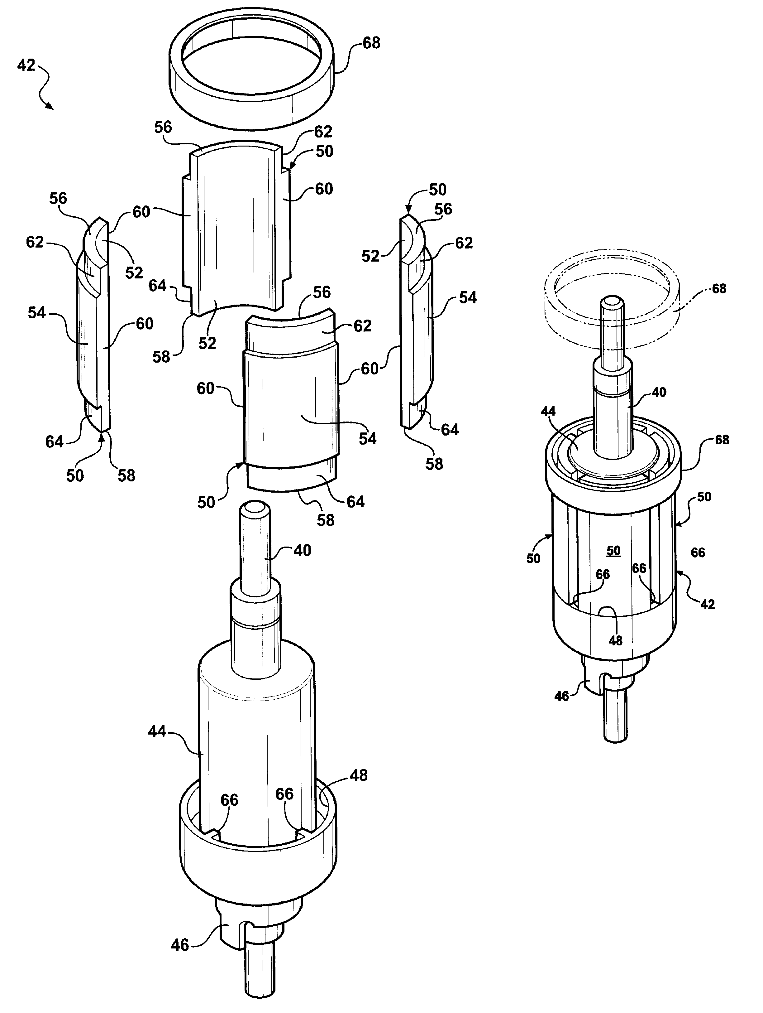
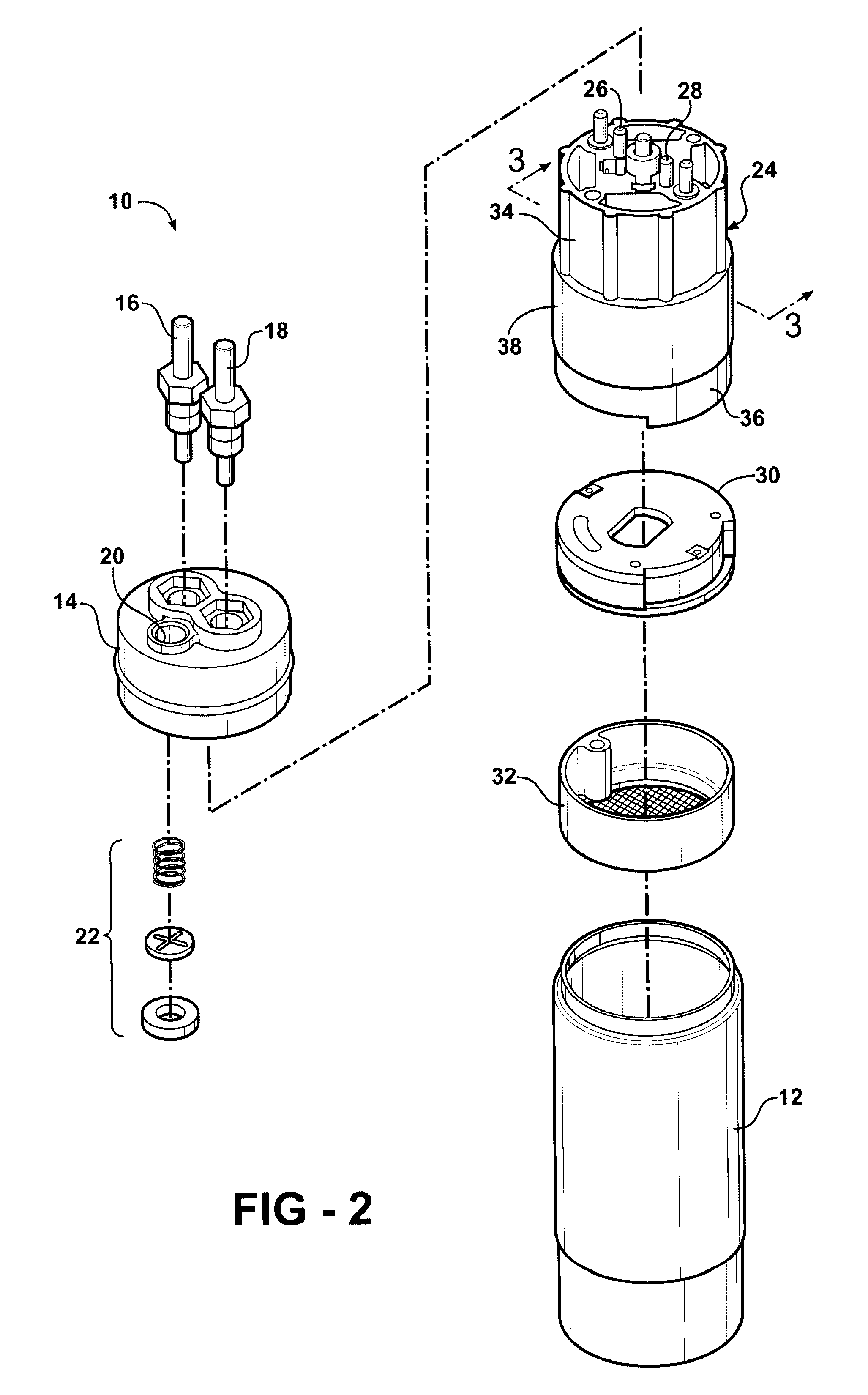
[0026]Referring now to FIG. 2, an exploded view of the pump 10 is depi...


PUM

PropertyMeasurementUnit
electro-magnetic fieldaaaaaaaaaa
metallicaaaaaaaaaa
rotationaaaaaaaaaa

Abstract

A BLDC electric motor assembly (24) includes a rotor (42) having a plurality of magnet segments (50) securely retained thereabout by an annular ring (68) which is shrunk in situ in an electromagnetic forming operation. The magnet segments (50) are formed with tongues (62, 64) on their upper and lower ends (56, 58). One tongue (64) seats in a retaining pocket (48) molded on the rotor shaft (40), whereas the other tongue (62) provides a ledge into which the ring (68) seats. After the magnet forming operation, wherein the ring (68) is shrunk, the outer surface of the ring (68) is flush with the outer surfaces (54) of the magnet segments (50).

Description

CROSS REFERENCE TO RELATED APPLICATIONS[0001]None.BACKGROUND OF THE INVENTION[0002]1. Field of the Invention[0003]This invention relates generally to a brushless direct current (BLDC) motor assembly, and more particularly toward an improved method and structure for attaching permanent magnet segments on a rotor of the BLDC motor assembly.[0004]2. Related Art[0005]With the introduction of electronic control systems for electric motors, the industry objectives of long life, efficiency, reliability and low EM interference have become achievable. This is, in part, due to the advent of brushless direct current (BLDC) motor technology.[0006]BLDC motor assemblies include a rotor assembly which is disposed for powered rotation within a stator in response to an electromagnetic field generated by the stator. The rotor of a BLDC motor includes a plurality of magnetic segments arrayed in equal arcuate increments about its exterior surface. Typical examples include 4 magnetic segments, each span...

Claims


Application Information

Patent Timeline
Patent Type & Authority Patents(United States)
IPC IPC(8): H02K21/12
CPCF02M37/08H02K1/278H02K15/03H02K5/225H02K11/0073Y10T29/49009H02K2211/03Y10T29/53143Y10T29/49011Y10T29/49012H02K11/33H02K29/08H02K1/28H02K5/132
Inventor ACHOR, KYLE D.
Owner CARTER FUEL SYST
Features
  • R&D
  • Intellectual Property
  • Life Sciences
  • Materials
  • Tech Scout
  • Unparalleled Data Quality
  • Higher Quality Content
  • 60% Fewer Hallucinations
Learn More