Supercharge Your Innovation With Domain-Expert AI Agents!

Semiconductor test system with self-inspection of electrical channel for Pogo tower

a test system and self-inspection technology, applied in continuity testing, short-circuit testing, instruments, etc., can solve the problems of large cost loss, serious event of taking back, and affecting the reputation of the company, so as to achieve the effect of reducing the cost of the test system and reducing the cos

Active Publication Date: 2010-12-07
KING YUAN ELECTRONICS
View PDF2 Cites 4 Cited by
  • Summary
  • Abstract
  • Description
  • Claims
  • Application Information

AI Technical Summary

Problems solved by technology

If the test bench or equipment is in failure or out of order, big loss in cost will be incurred.
In addition, in many occasions of incurring failure or an abnormal condition, the bench or equipment itself will not inform or notify the situation and it is hard to trace back when the failure or abnormal condition starts, which quite often results in a serious event of taking back.
Not only loss of cost is generated, but also reputation of the company will be affected.
As the Pogo pins obtain test parameters and send them back through electrical channels on a load board, due to that the Pogo pins on the Pogo tower or the electrical channels are up to many hundreds, inspection of electrical properties thereof indeed meets with problem.
Further, since the Pogo pins and the electrical channels play a rather important role, once one inside them is damaged or in an abnormal condition, such as in an unexpected open circuit or short circuit, or in leakage, the whole test quality or test result will be affected.
Such inspections waste much time and human labors.
As far as the existing techniques are concerned, there is no provision of a system or method of inspecting an electrical channel for a Pogo tower capable of rapid and effective inspection and adaptively for use in all kinds of equipments produced by the enterprises.

Method used


Image

  • Semiconductor test system with self-inspection of electrical channel for Pogo tower
  • Semiconductor test system with self-inspection of electrical channel for Pogo tower
  • Semiconductor test system with self-inspection of electrical channel for Pogo tower

Examples


Embodiment Construction

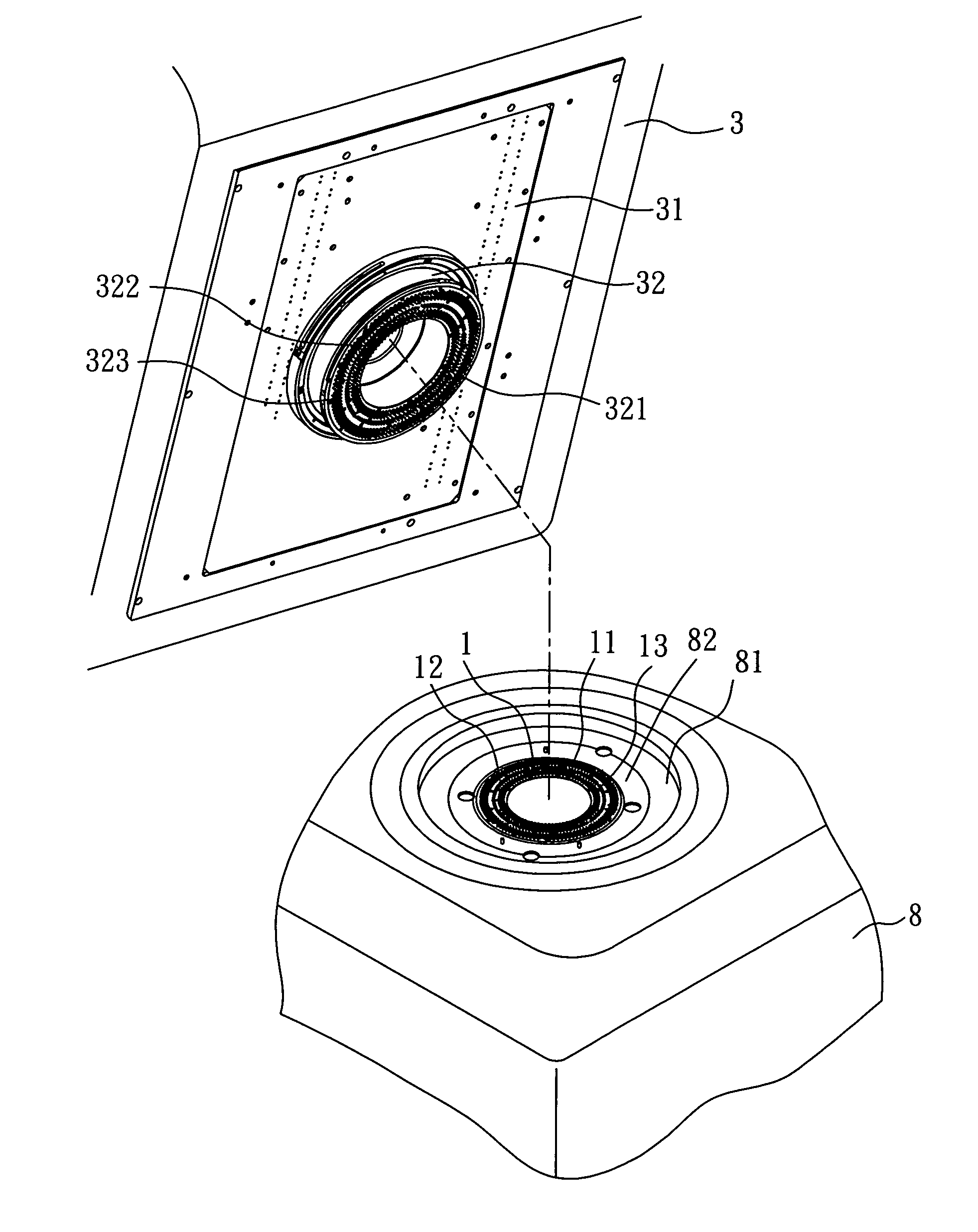
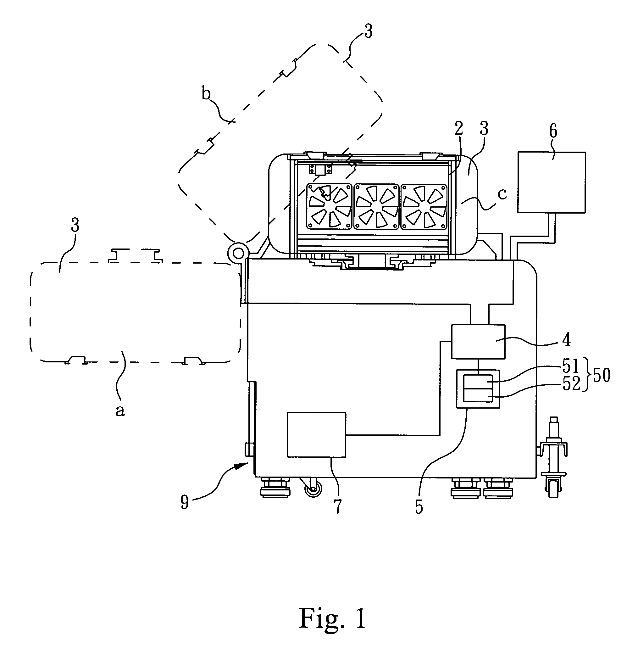
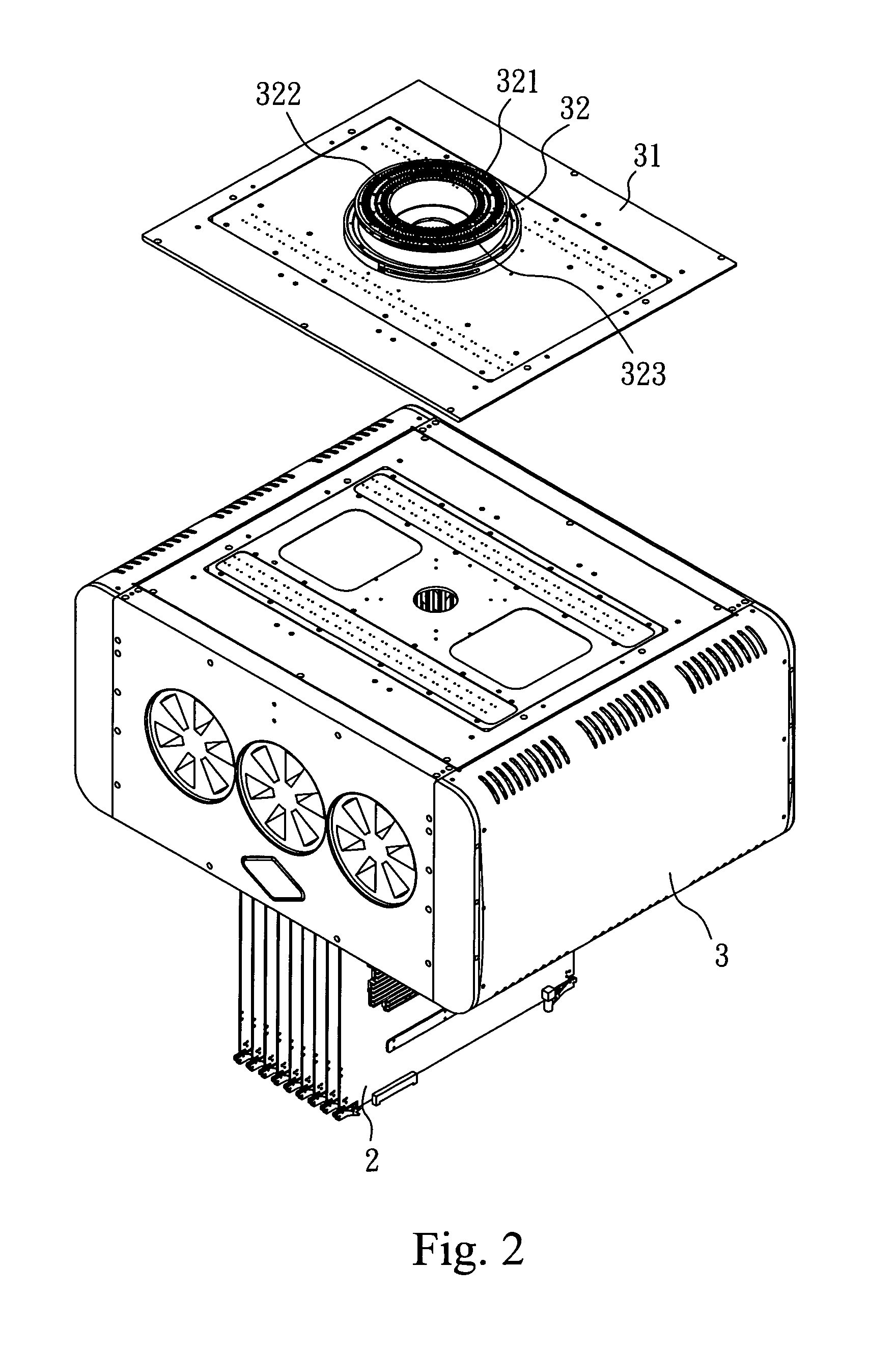
[0027]Please refer to FIGS. 1, 2 and 3 concurrently. FIG. 1 is a schematic diagram showing a semiconductor test equipment as a whole, provided with a semiconductor test system with self-inspection of an electrical channel for a Pogo tower, according to a preferred embodiment of the invention. FIG. 2 is a perspective view showing a tester head, being located in position a, according to a preferred embodiment of the invention. FIG. 3 is a three-dimensional diagram showing a tester head, being located in position b, and a base (chassis) according to a preferred embodiment of the invention. The figures show a test bench 9, on which is provided with a tester head 3. The tester head 3 includes a load board 31, a Pogo tower 32, and a plurality of pin electronics cards (PE cards) 2 inserted therein.

[0028]Please refer to FIG. 4 at the same time. FIG. 4 shows a system structure of a semiconductor test system with self-inspection of an electrical channel for a Pogo tower according to a preferr...


PUM


Abstract

A semiconductor test system with self-inspection of an electrical channel for a Pogo tower is disclosed, which provides a short board and closed loops are formed respectively by providing various kinds of contacts to correspondingly electrically contact various kinds of Pogo pins in the Pogo tower on a load board. A self-inspection controller outputs different inspection signals, through the above-mentioned closed loops, respectively to each power channel, each I / O channel and each drive channel, and a plurality of parameter detection units detect response signals, and the response signals are judged by the self-inspection controller. Based on it, before inspecting a wafer to be tested, the invention is capable of self-inspecting each electrical channel and each Pogo pin on the Pogo tower to see if they are respectively in a normal condition, either in an open or short circuit, or if there exists a leakage condition.

Description

BACKGROUND OF THE INVENTION[0001]1. Field of the Invention[0002]The present invention relates to a semiconductor test system with self-inspection of an electrical channel for a Pogo tower and, more particularly, to a test system for use in a test equipment for IC package.[0003]2. Background of the Invention[0004]In the industry of semiconductor package test, the test bench (machine) for testing dominates an absolutely important role. If the test bench or equipment is in failure or out of order, big loss in cost will be incurred. In addition, in many occasions of incurring failure or an abnormal condition, the bench or equipment itself will not inform or notify the situation and it is hard to trace back when the failure or abnormal condition starts, which quite often results in a serious event of taking back. Not only loss of cost is generated, but also reputation of the company will be affected.[0005]Pogo pins are used to directly contact a chip or wafer to be tested for testing. As...

Claims


Application Information

Patent Timeline
Patent Type & Authority Patents(United States)
IPC IPC(8): G01R31/02
CPCG01R31/024G01R31/2889G01R35/00G01R31/52G01R31/54
Inventor CHANG, CHUNG LUNG
Owner KING YUAN ELECTRONICS
Features
  • R&D
  • Intellectual Property
  • Life Sciences
  • Materials
  • Tech Scout
  • Unparalleled Data Quality
  • Higher Quality Content
  • 60% Fewer Hallucinations
Learn More