

Wall materials bracket and insulating wall structure
a technology of wall materials and brackets, which is applied in the direction of washstands, lightening support devices, scaffold accessories, etc., can solve the problem of hard work of fixing wall materials
- Summary
- Abstract
- Description
- Claims
- Application Information
AI Technical Summary
Benefits of technology
Problems solved by technology
Method used
Image

Examples
first embodiment
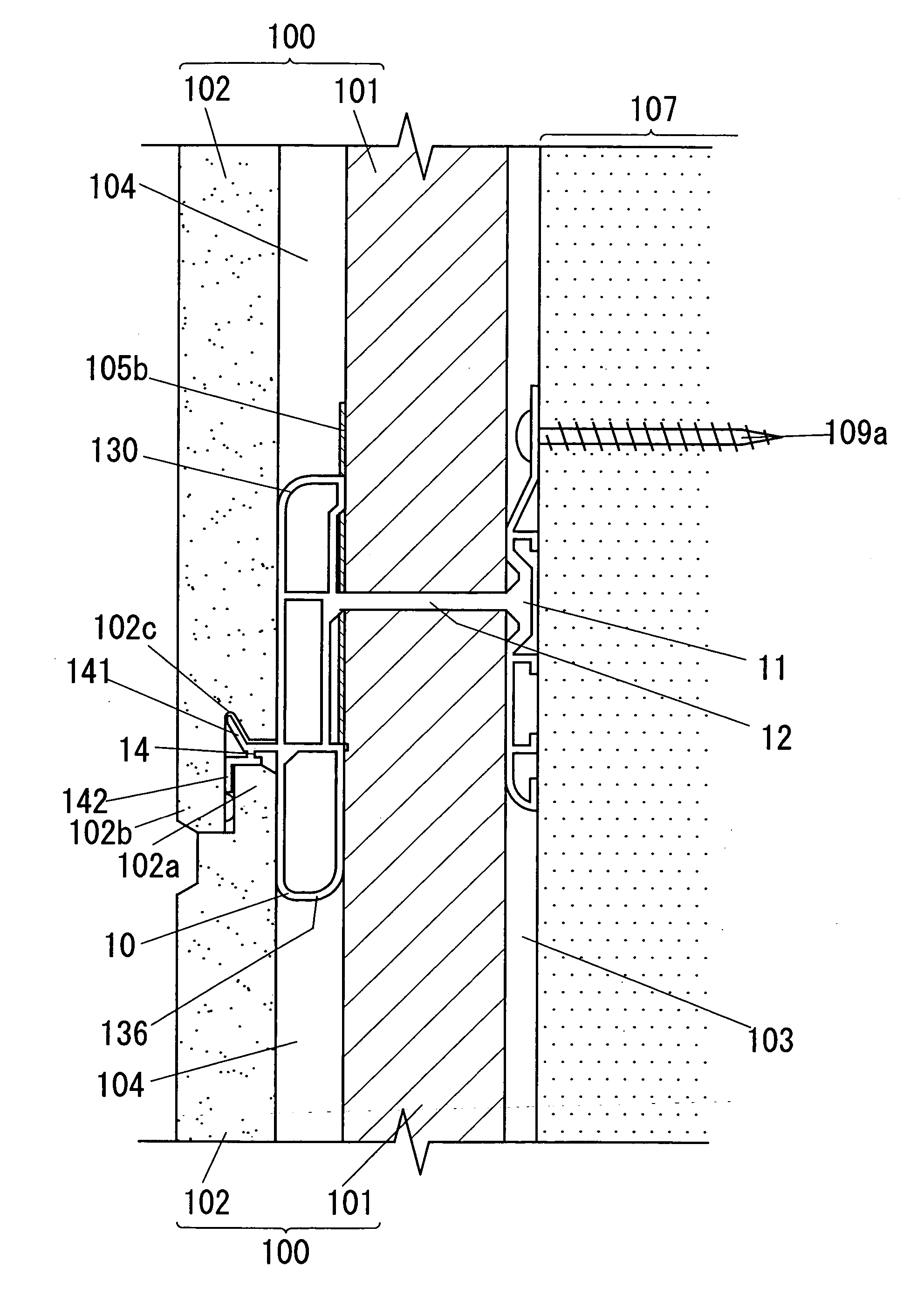
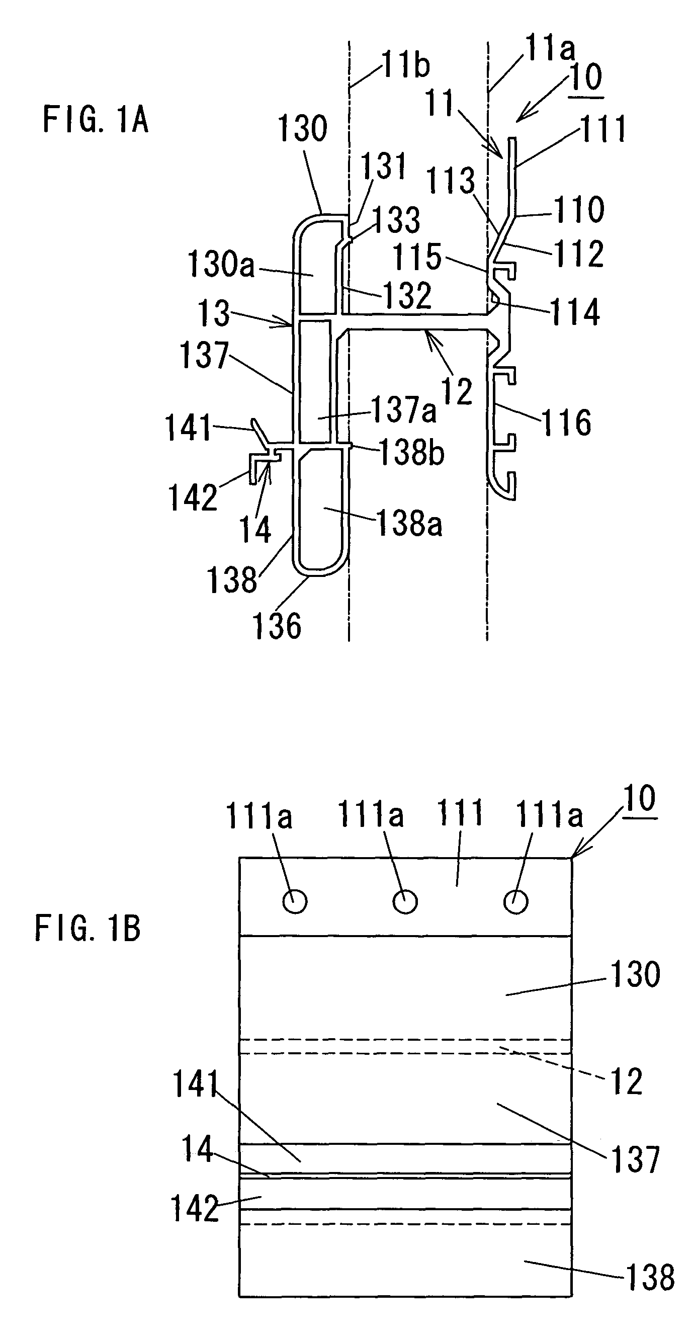
[0047]The bracket 10 is characterized by a leaning means for leaning the insulation 101 put on the catching piece 12 against the wall substrate 107. The leaning means of the first embodiment is constructed with the upper half 111, the slope 113, the cavity 132 and the strip 133.
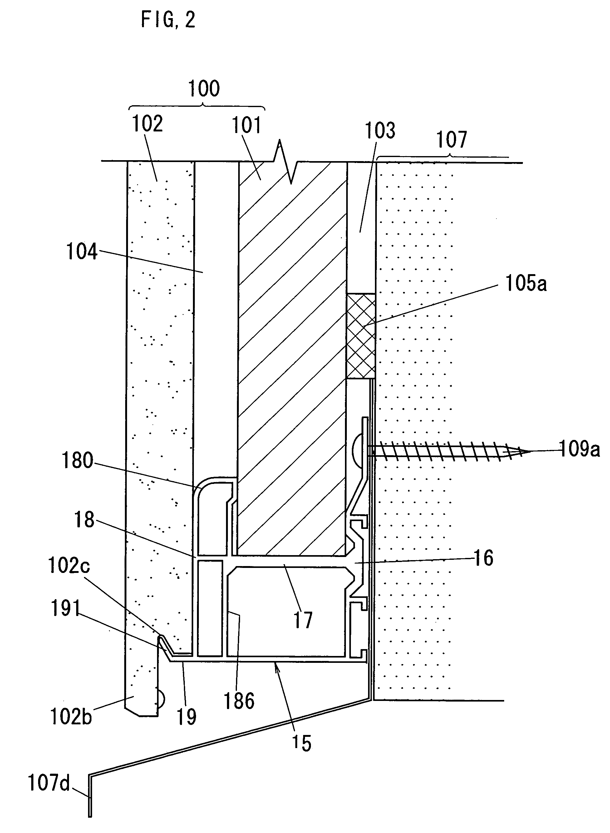
[0048]The wall materials bracket 15 has a flat plate-shaped base piece 16 and a flat plate-shaped catching piece 17 in the same way as those of the bracket 10, and also has a spacing piece 18 and a holding piece 19 (see FIG. 2). The base piece 16 is interposed between the wall substrate 107 and insulation 101 on the catching piece 17 to form the air layer 103 between them. The catching piece 17 holds the bottom end of the insulation 101 to restrict its downward movement. The spacing piece 18 is further subdivided into upper and lower parts 180 and 186 by the catching piece 17, and the upper part 180 is formed in the same way as that of the spacing piece 13, while the lower end of the lower part 186 is joined ...
second embodiment
[0069] since the left and right brackets 20 and 20 can be located in immediate proximity to the reentrant corner edge of the wall substrate 207, each bracket 20 can be fixed on each supplementary frame 207j directly fixed on the pillar of the frame 207i. The reentrant corner starters also have same advantage. Therefore, it is possible to firmly fix the wall materials 100 on the reentrant corner of the wall substrate 207 with the reentrant corner joiners (20) and the reentrant corner starters.
[0070]FIG. 13 shows wall materials brackets (30) of a third embodiment according to the present invention, and FIG. 14 shows an insulating wall structure of the third embodiment. As shown in these FIGS., the bracket 30 is used together with other same brackets as salient corner joiners (30), wall materials brackets as salient corner starters (not shown), wall materials brackets as reentrant corner joiners, wall materials brackets as reentrant corner starters (not shown), wall materials brackets ...
third embodiment
[0075] it is possible to firmly fix the wall materials 100 on the salient corner of the wall substrate 207 with the salient corner joiners (30) and the salient corner starters. Especially, the L-shaped external wall board 102a can be firmly fixed on the salient corner.
[0076]In a modified embodiment, as shown in FIG. 15, the insulating wall structure includes airtight tape 105b and waterproof materials 206. The airtight tape 105b seals between insulations 101 and 101 neighboring each other in the insulations (101) fixed and arranged side by side with above each bracket. The waterproof materials 206 waterproofs between external wall boards 102 and 102 neighboring each other in the external wall boards (102) fixed and arranged side by side with each bracket. In addition, the insulation 101 has a width substantially equal to one or more times width (e.g., one time width in FIG. 15) of the external wall board 102. As a result, since every side (vertical surface, but not the front or back...
PUM
 Abstract
Description
Claims
Application Information