Vehicle front structure
a front structure and vehicle technology, applied in the direction of vehicle sub-unit features, roofs, tractors, etc., can solve the problems of ineffective receiving collision load and ineffective transmission of collision load to the rear side of the vehicl
- Summary
- Abstract
- Description
- Claims
- Application Information
AI Technical Summary
Benefits of technology
Problems solved by technology
Method used
Image
Examples
first embodiment
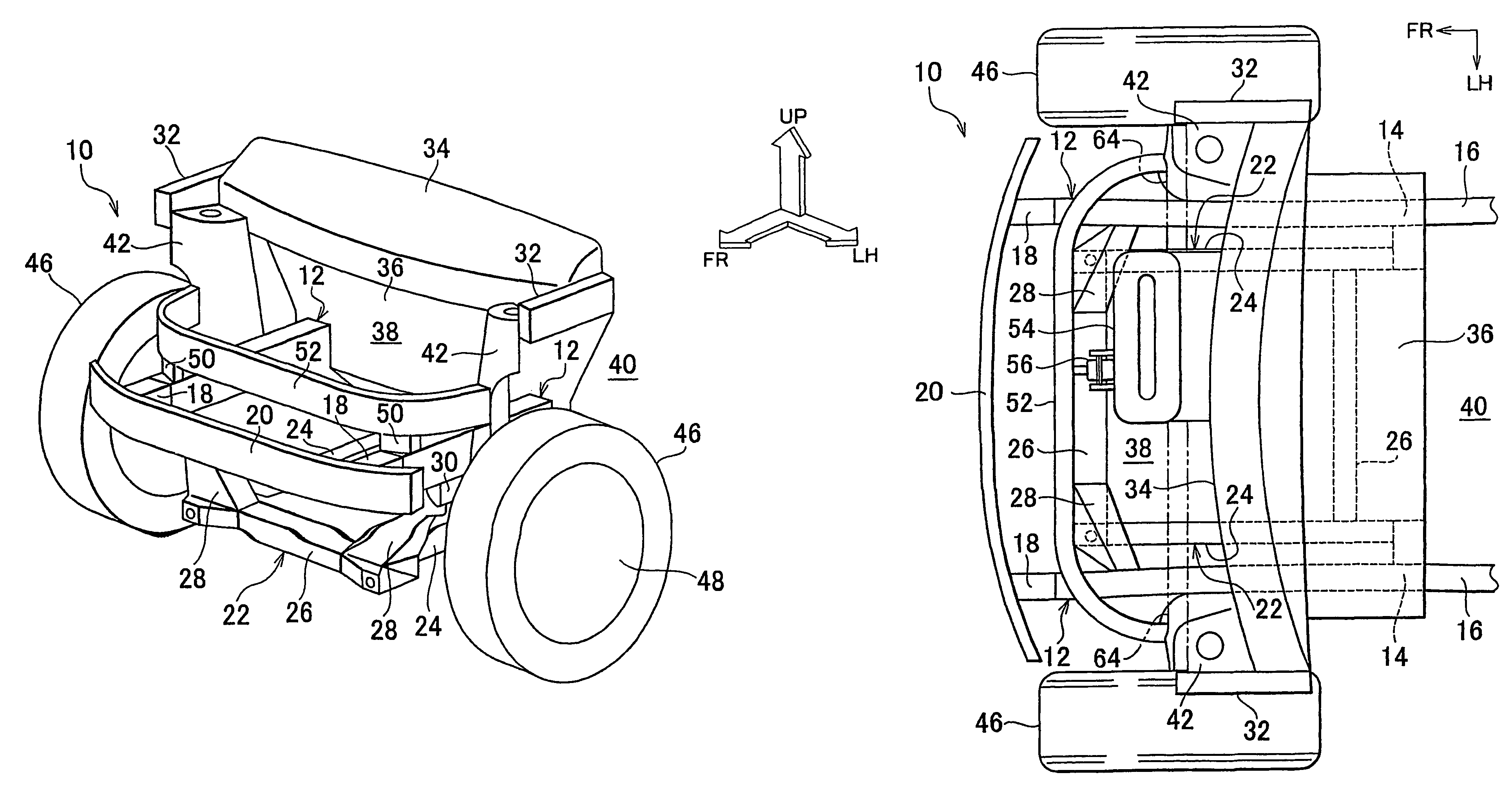
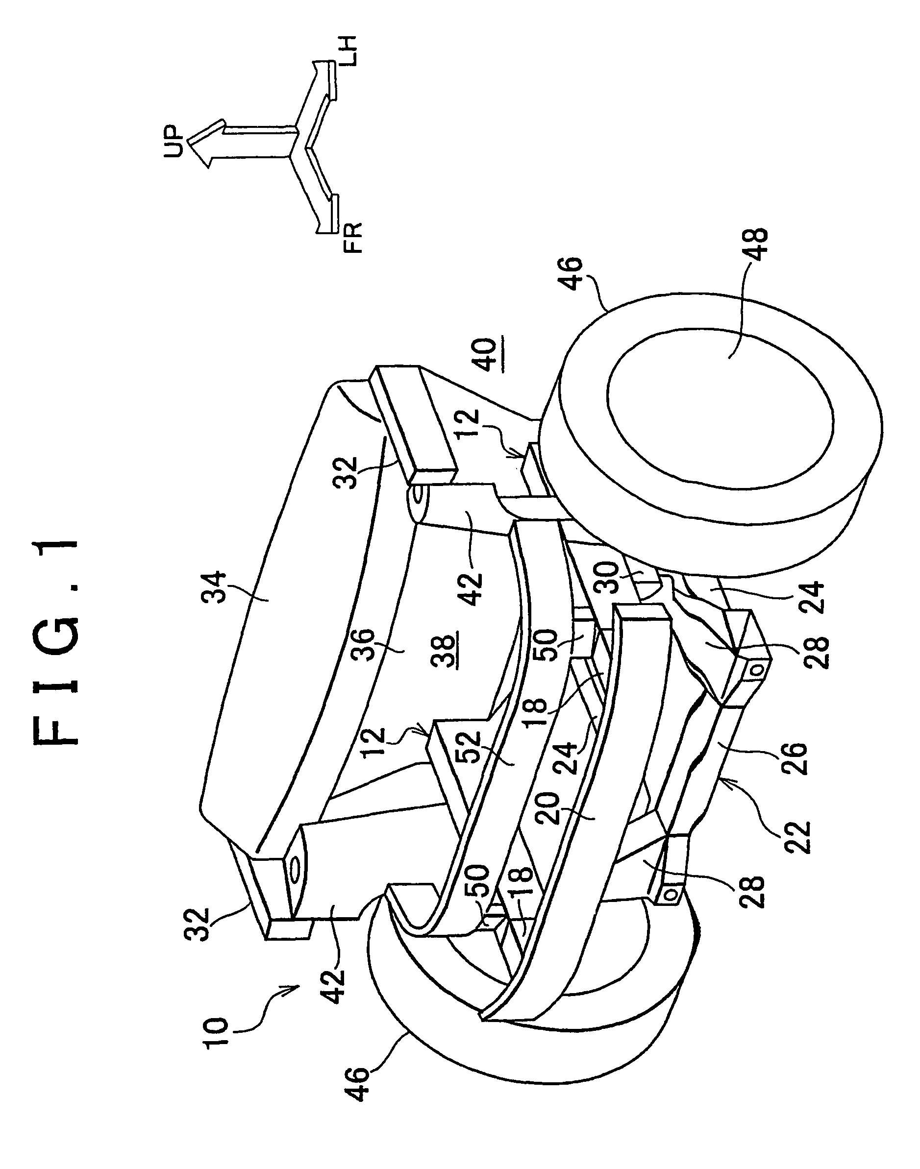
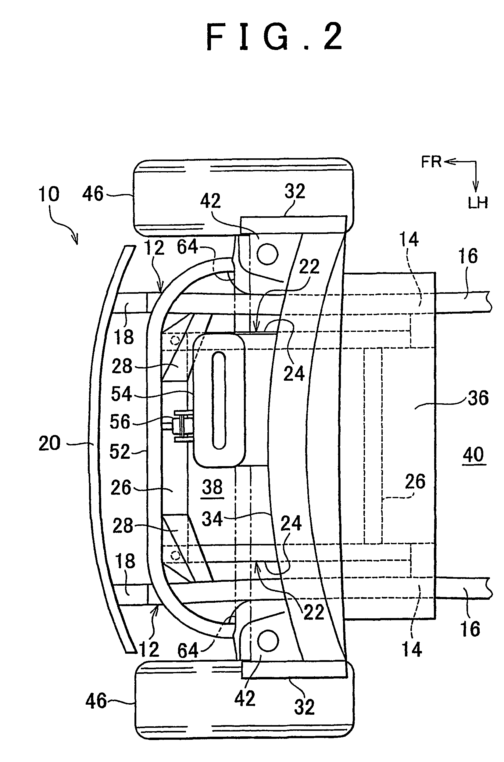
[0043]FIG. 1 is a schematic perspective view showing a vehicle front structure 10 according to a first embodiment of the invention when diagonally seen from a position ahead of, and on a left side of a vehicle. Further, FIG. 2 is a plan view showing the vehicle front structure 10 according to the first embodiment of the invention when seen from above the vehicle. FIG. 3 is a lateral view showing the vehicle front structure 10 according to the first embodiment of the invention when seen from a position on the left side of the vehicle. In figures, an arrow FR indicates a position ahead of the vehicle, an arrow LH indicates a position on the left side of the vehicle, and an arrow UP indicates a position above the vehicle.
[0044]The vehicle front structure 10 according to the embodiment includes paired front side members 12 having a long rectangular tube shape, which serve as side members. The paired front side members 12 are disposed along a vehicle longitudinal direction at a right sid...
second embodiment
[0073]FIG. 5 is a schematic perspective view showing a vehicle front structure 70 according to a second embodiment of the invention when diagonally seen from a position ahead of, and on the left side of the vehicle.
[0074]The vehicle front structure 70 according to the second embodiment of the invention has substantially the same configuration as that of the vehicle front structure 10 according to the first embodiment. However, the vehicle front structure 70 is different from the vehicle front structure 10 in the following points.
[0075]In the vehicle front structure 70 according to the second embodiment, the cross member 52 is made of highly air-tight material such as an extrusion material. Intake air ports 72 are provided at both ends of the cross member 52. Each of the intake air ports 72 is opened into an inside of the corresponding suspension tower 42.
[0076]The power unit 54 (not shown in FIG. 5) and the cross member 52 are not connected with each other using the torque rod 56 th...
third embodiment
[0081]FIG. 7 is a schematic perspective view showing a vehicle front structure 80 according to a third embodiment of the invention when diagonally seen from a position ahead of, and on a left side of a vehicle.
[0082]The vehicle front structure 80 according to the third embodiment has substantially the same configuration as that in the first embodiment. However, the vehicle front structure 80 according to the third embodiment is different from the vehicle front structure 10 according to the first embodiment in the following points.
[0083]In the vehicle front structure 80 according to the third embodiment, the paired braces 50 that are provided in the first embodiment are not provided. The cross member 52 is not connected with the paired front side members 12, and is disposed above the paired front side members 12 so as to be separated from the paired front side members 12.
[0084]In the third embodiment as well, it is possible to obtain the same actions and effects as those obtained in ...
PUM
 Abstract
Description
Claims
Application Information
 - R&D
- Intellectual Property
- Life Sciences
- Materials
- Tech Scout
- Unparalleled Data Quality
- Higher Quality Content
- 60% Fewer Hallucinations
Browse by: Latest US Patents, China's latest patents, Technical Efficacy Thesaurus, Application Domain, Technology Topic, Popular Technical Reports.
© 2025 PatSnap. All rights reserved.Legal|Privacy policy|Modern Slavery Act Transparency Statement|Sitemap|About US| Contact US: help@patsnap.com


