Image pickup apparatus

a technology of image pickup and spherical tube, which is applied in the direction of television systems, instruments, transportation and packaging, etc., can solve the problems of power consumption and operation durability, inconvenience, and inability to detect the exchange of photographic lenses in the power-off state, and achieve the effect of effectively removing the attached dust and preventing the degradation of image quality

Inactive Publication Date: 2010-12-14
CANON KK
View PDF10 Cites 0 Cited by
  • Summary
  • Abstract
  • Description
  • Claims
  • Application Information

AI Technical Summary

Benefits of technology

[0008]The present invention provides an image pickup apparatus which is capable of detecting, when the power is turned on again, whether or not a photographic lens-mounting / removing operation has been performed in the power-off state so as to effectively remove dust attached to an optical member, to thereby prevent degradation of image quality.
[0011]A dust-removing mechanism can be driven based on the result of the determination, so that it is possible to effectively remove dust attached to the optical member, to thereby avoid picking up the image of the dust and prevent degradation of image quality.
[0030]The first control can cause the vibrator unit to be driven for a predetermined time period, and the second control can cause the vibrator unit to be driven for a longer time period than the predetermined time period.

Problems solved by technology

However, in the image pickup apparatuses disclosed in the above-mentioned Patent Publications, in each of which mounting / removing of a photographic lens is electrically detected, it is impossible to detect the exchange of photographic lenses performed in the power-off state.
On the other hand, if the dust-removing mechanism is configured to be operated whenever the power is turned on, irrespective of whether or not a lens mounting / removing operation has been performed, an inconvenience occurs when the power is repeatedly turned on and off over a short time period without mounting or demounting a lens or when the apparatus returns from a sleep state (power-saving state where the operation of the apparatus is temporarily stopped) to an ON state.
That is, the dust-removing mechanism is operated even when it is not required, which is undesirable in terms of power consumption and operation durability.

Method used


Image

  • Image pickup apparatus
  • Image pickup apparatus
  • Image pickup apparatus

Examples


first embodiment

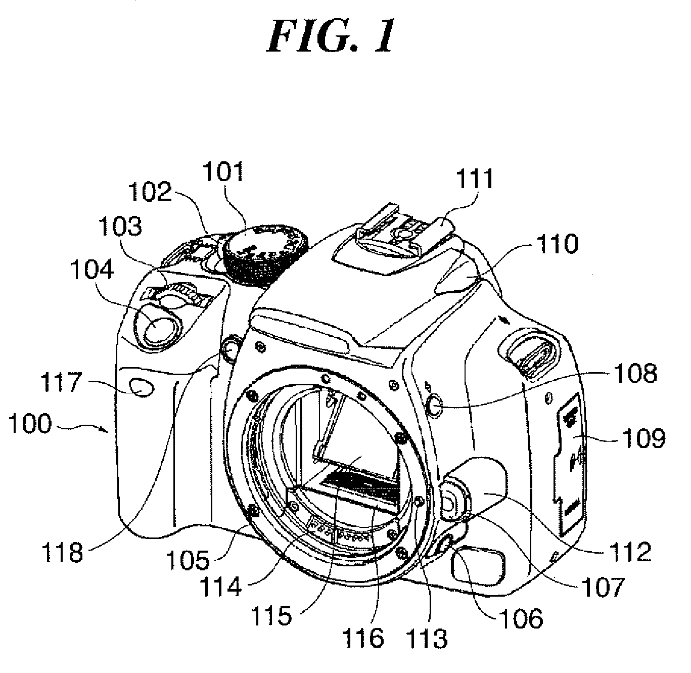
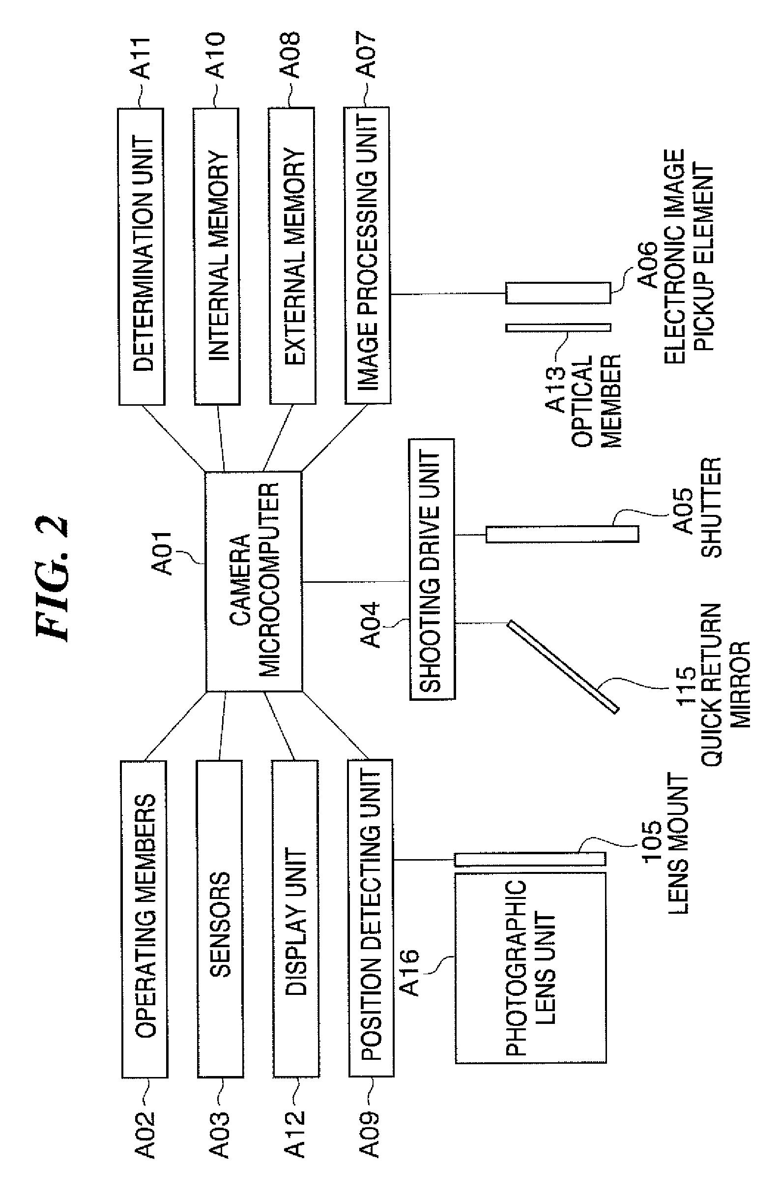
[0072]FIG. 1 is a perspective view of a digital single-lens reflex camera according to the present invention, as viewed from an object side, in a state where a photographic lens unit is removed therefrom. FIG. 2 is a control block diagram of the digital single-lens reflex camera.

[0073]As shown in FIG. 1, the digital single-lens reflex camera (image pickup apparatus) according to the first embodiment has a lens mount 105 provided as a part for use in mounting the photographic lens unit A16 (see FIG. 2) to a camera body 100 via a bayonet mechanism. The camera body 100 has communication pins 114 projecting therefrom for identifying the type of the photographic lens unit A16 mounted to the camera body 100.

[0074]Next, an operation carried out by a photographer before shooting will be described with reference to FIGS. 1 and 2.

[0075]As shown in FIGS. 1 and 2, when the photographer mounts the photographic lens unit A16 to the camera body 100 and turns a power switch member 102 to its ON pos...

second embodiment

[0163]The tapered part 400-c of the linkage lever 400 is identical in shape to the tapered part 200-c of the linkage lever 200. Further, a mechanism for moving the linkage lever 400 along the lens optical axis in a manner interlocked with a photographic lens mounting / removing operation is the same as the mechanism, described in the second embodiment, for moving the linkage pin 200 along the lens optical axis in a manner interlocked with the photographic lens mounting / removing operation.

third embodiment

[0164]The linkage lever 400 is formed with a detected arm (movable unit) 400-a for being inserted in the detector part of the PI 302, and a lever dowel 400-b for fixing one end of the toggle spring 303. The detected arm 400-a and the lever dowel 400-b are identical in shape to the detected arm 300-a and the lever dowel 300-b formed in the linkage lever 300 described in the

[0165]A motor base plate 402 is formed with a base plate dowel 402-d for fixing the other end of the toggle spring 303, a PI mounting part 402-c for mounting the PI 302 for detecting the position of the linkage lever 400, and a slot 402-b for preventing rotation of the linkage lever 400. The base plate dowel 402-d, the PI mounting part 402-c, and the slot 402-b are identical in shape to the base plate dowel 301-b, the PI mounting part 301-c, and the slot 301-b for preventing rotation, in the third embodiment.

[0166]FIG. 33 is a cross-sectional view of the mirror box 401 with the lens mount 105 rigidly secured theret...


PUM


Abstract

An image pickup apparatus which is capable of effectively removing dust attached to an optical member due to mounting / removing of a photographic lens in a power-off state, to thereby prevent degradation of image quality. In the image pickup apparatus, when position information of a contact brush that moves in a manner interlocked with mounting / removing of the photographic lens differs immediately after execution of power-on operation from position information obtained immediately after execution of power-off operation, it is determined that photographic lens mounting / removing operation was carried out during power-off, and a camera microcomputer outputs a warning advising cleaning of the optical member.

Description

BACKGROUND OF THE INVENTION[0001]1. Field of the Invention[0002]The present invention relates to an image pickup apparatus, such as a digital single-lens reflex camera, on which has a photographic lens is removably held.[0003]2. Description of the Related Art[0004]Conventionally, in an image pickup apparatus of the above-mentioned type, countermeasures are taken to prevent degradation of image quality due to dust attached to an optical member, such as a low-pass filter, disposed between a photographic lens and an image pickup element that converts light incident thereon from the photographic lens into an electric signal.[0005]For example, an image pickup apparatus has been made commercially practical in which a member disposed between a photographic lens and an image pickup element is ultrasonically vibrated to thereby remove dust attached to the member. Further, there have been proposed an image pickup apparatus in which the number of times of attachment / detachment of a detachable ...

Claims


Application Information

Patent Timeline
Patent Type & Authority Patents(United States)
IPC IPC(8): G03B17/00
CPCG02B27/0006G03B17/02G03B17/14G03B17/18H04N5/2171H04N5/2254H04N2101/00H04N23/811H04N23/55H04N23/60
Inventor HIRAI, FUTOSHI
Owner CANON KK
Why Eureka
Try Eureka