Check patentability & draft patents in minutes with Patsnap Eureka AI!

System and methods for improved ultrasound imaging

a technology of ultrasound imaging and system, applied in the field of ultrasound imaging, can solve the problems of inability to adjust, and inability to achieve the desired effect,

Inactive Publication Date: 2010-12-14
CARESTREAM HEALTH INC
View PDF32 Cites 11 Cited by
  • Summary
  • Abstract
  • Description
  • Claims
  • Application Information

AI Technical Summary

Benefits of technology

[0010]The foregoing needs can be addressed by systems and methods for improving the resolution and quality of an image formed by signals from an array of receivers. Multiple receivers introduce variations in arrival times that can be less than the period of an operating signal, and also less than the period associated with a sampling operation. Thus, multiple receivers allow sampling of fine features of reflected signals that would be considered beyond the resolution associated with the operating signal. Use of multiple receivers also provides an effective sampling rate that is greater than the sampling rate of an individual receiver. Similar advantages can be obtained using multiple transmitters. Such advantageous features can be used to obtain high resolution images of objects in a medium in applications such as ultrasound imaging.
[0028]In one embodiment of the apparatus, the spatial resolution limit allows resolving of two objects in the medium that are closer together than approximately 100 micrometers when the ultrasound energy has a central peak frequency of approximately 3.5 MHz. In one embodiment, the processor combines the plurality of digital echo signals by a process that includes selecting a first digital echo signal associated with a first receiver, and performing a plurality of time-shift combinations of the first digital echo signal with one or more digital echo signals associated with one or more other receivers about a selected time window of the first signal. Each of the plurality of combinations has a quality value indicative of a quality of the combination.
[0033]In one embodiment of the method, the spatial resolution limit allows resolving of the two objects in the medium that are closer together than approximately 100 micrometers when the ultrasound energy has a central peak frequency of approximately 3.5 MHz. In one embodiment, the step of digitally combining the signals includes digitally sampling the signals so as to produce a plurality of digital echo signals. The step further includes selecting a first digital echo signal associated with a first receiver. The step further includes performing a plurality of time-shift combinations of the first digital echo signal with one or more digital echo signals associated with one or more other receivers about a selected time window of the first signal. Each of the plurality of combinations has a quality value indicative of a quality of the combination.

Problems solved by technology

Based on such an operation, one can see that the resolution and quality of the image formed can be limited by the size of the scanline element.
However, such a change can be accompanied by undesired effects.

Method used


Image

  • System and methods for improved ultrasound imaging
  • System and methods for improved ultrasound imaging
  • System and methods for improved ultrasound imaging

Examples


Embodiment Construction

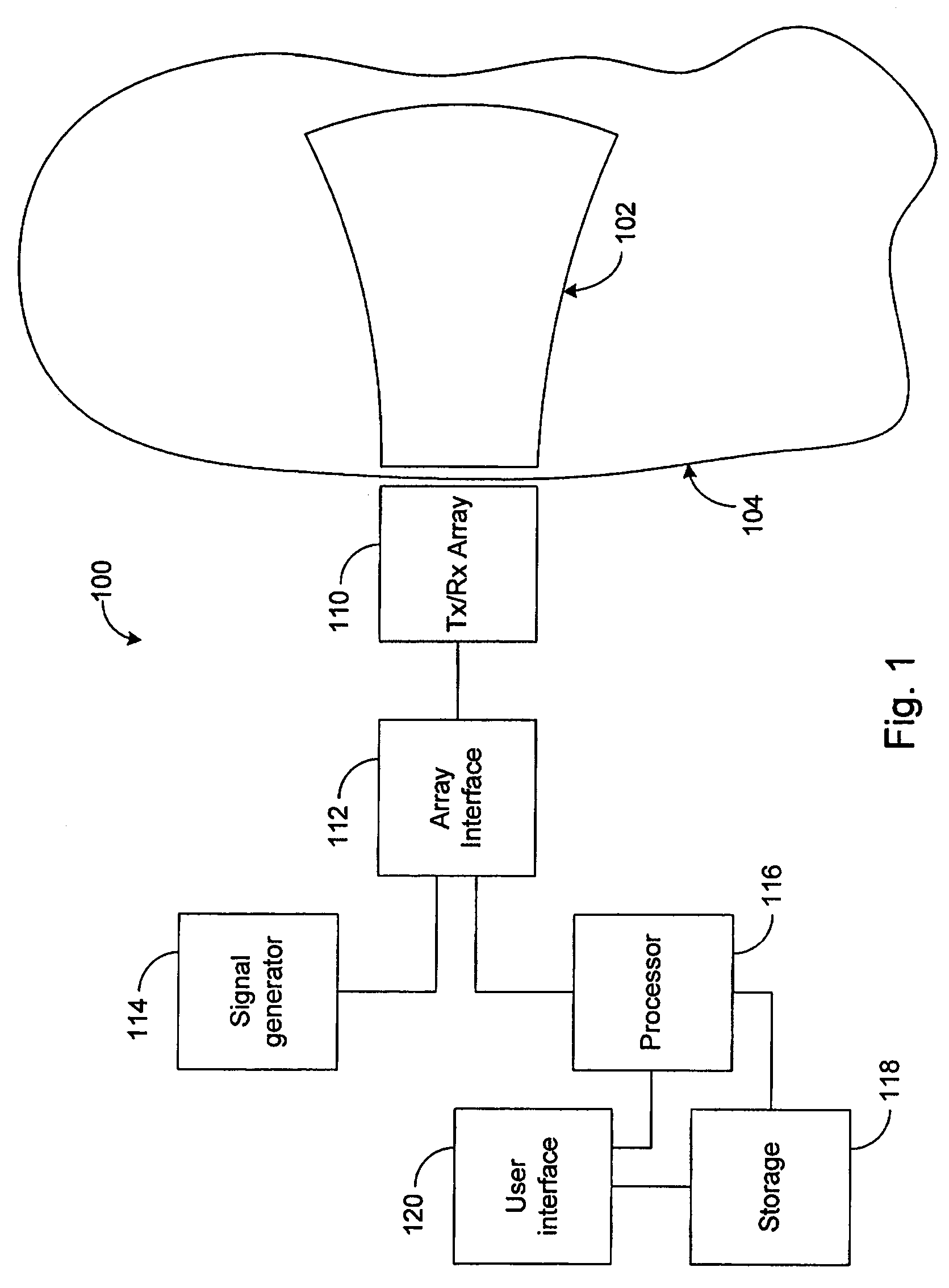
[0086]The present teachings generally relate to systems and methods for forming an image of a portion of a medium. FIG. 1 shows a block diagram of one embodiment of an imaging device 100 that includes an array 110 of transducers. A transducer can represent a transmitter or a receiver. As is known, some transducers can operate as transmitters and as receivers. Thus for the purpose of description, a transducer can represent a transmitter, a receiver, or a combination thereof.

[0087]As shown in FIG. 1, the imaging device 100 further includes an array interface 112 that facilitates operation of the array 110 of transducers. The array interface 112 may, for example, multiplex and / or demultiplex a plurality of signals to and / or from transmitters and / or receivers. The transducer array 110 via the interface 112 may be supplied with a signal from a signal generator 114. The operation of the interface 112 in providing the signal to the array 110 and / or readout of the received signals from the ...


PUM


Abstract

Systems and methods are disclosed for improving the resolution and quality of an image formed by signals from an array of receivers. Multiple receivers introduce variations in arrival times that can be less than the period of an operating signal, and also less than the period associated with a sampling operation. Thus, multiple receivers allow sampling of fine features of reflected signals that would be considered beyond the resolution associated with the operating signal. Use of multiple receivers also provides an effective sampling rate that is greater than the sampling rate of an individual receiver. Similar advantages can be obtained using multiple transmitters. Such advantageous features can be used to obtain high resolution images of objects in a medium in applications such as ultrasound imaging.

Description

BACKGROUND[0001]1. Field[0002]The present teachings generally relate to the field of imaging using waves and more particularly, to systems and methods for improving the resolution of images obtained by an array of transmitters and receivers.[0003]2. Description of the Related Art[0004]Imaging devices such as ultrasound devices transmit a signal into a medium, and measure reflections from various features in the medium. An image of a given feature can be reconstructed based on quantities such as intensity and frequency of the reflected signal from that feature. To form the image, one needs to somehow determine the relative location of the feature with respect to the imaging device, and in particular, to a location of a receiving element of the device.[0005]Conventional ultrasound devices typically have an array of transmitter-receiver pairs. In operation, each pair only “sees” along a line, commonly referred to as a scanline, that extends from the pair into the medium. With such an a...

Claims


Application Information

Patent Timeline
Patent Type & Authority Patents(United States)
IPC IPC(8): A61B8/00
CPCG01S7/52028G01S7/52046G01S15/8918G01S7/52003G01S7/52036G01S15/8927A61B8/4483A61B8/00G01S15/89G10K11/34
Inventor DAVIES, TIMOTHY J.EVANS, RICHARD
Owner CARESTREAM HEALTH INC
Features
  • R&D
  • Intellectual Property
  • Life Sciences
  • Materials
  • Tech Scout
  • Unparalleled Data Quality
  • Higher Quality Content
  • 60% Fewer Hallucinations
Learn More