
Reinforced venous access catheter

a venous access catheter and reinforcement technology, applied in the direction of catheters, multi-lumen catheters, coatings, etc., can solve the problems of limited structural strength, limited amount of pressure and flow rate that the catheter can support without damage, and inpractical and/or dangerous to insert and remove the catheter and the needl

Active Publication Date: 2010-12-14
ANGIODYNAMICS INC
View PDF16 Cites 45 Cited by
  • Summary
  • Abstract
  • Description
  • Claims
  • Application Information

AI Technical Summary

Benefits of technology

The reinforced catheter can withstand pressures up to 300 PSI and flow rates of 4 to 6 cc / sec, reducing the need for additional catheters and minimizing patient discomfort and procedural time, while maintaining atraumatic insertion and ease of use.

Problems solved by technology

When such procedures must be frequently repeated, it may be impractical and / or dangerous to insert and remove the catheter and the needle for each session.
Accordingly, their structural strength is limited by the thickness and type of material forming the catheter's walls.
The amount of pressure and flow rate that the catheter can support without damage is also limited.
If the maximum pressure the catheter can withstand (the burst pressure) or the maximum flow rate is exceeded, the catheter may be damaged or may completely fail possibly spilling fluids from the catheter into the body.
During high pressure injections, escaping fluid may also damage the surrounding tissues.
Conventional PICC catheters are unable to withstand the high pressures and flow rates associated with the introduction of visualization media which are often substantially above what is used for the infusion of medications.
Thus, it is often necessary to insert one or more additional catheters dedicated to the contrast media increasing patient discomfort and the time and costs associated with the procedure.
If the patient exhibits poor peripheral venous access, the insertion of an additional contrast media catheter may be difficult.

Method used


Image

  • Reinforced venous access catheter
  • Reinforced venous access catheter
  • Reinforced venous access catheter

Examples


Embodiment Construction

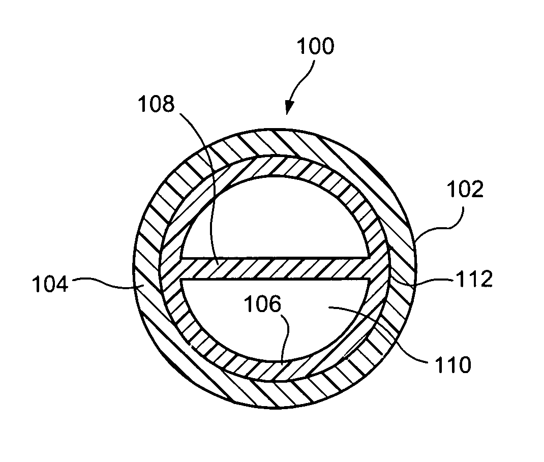
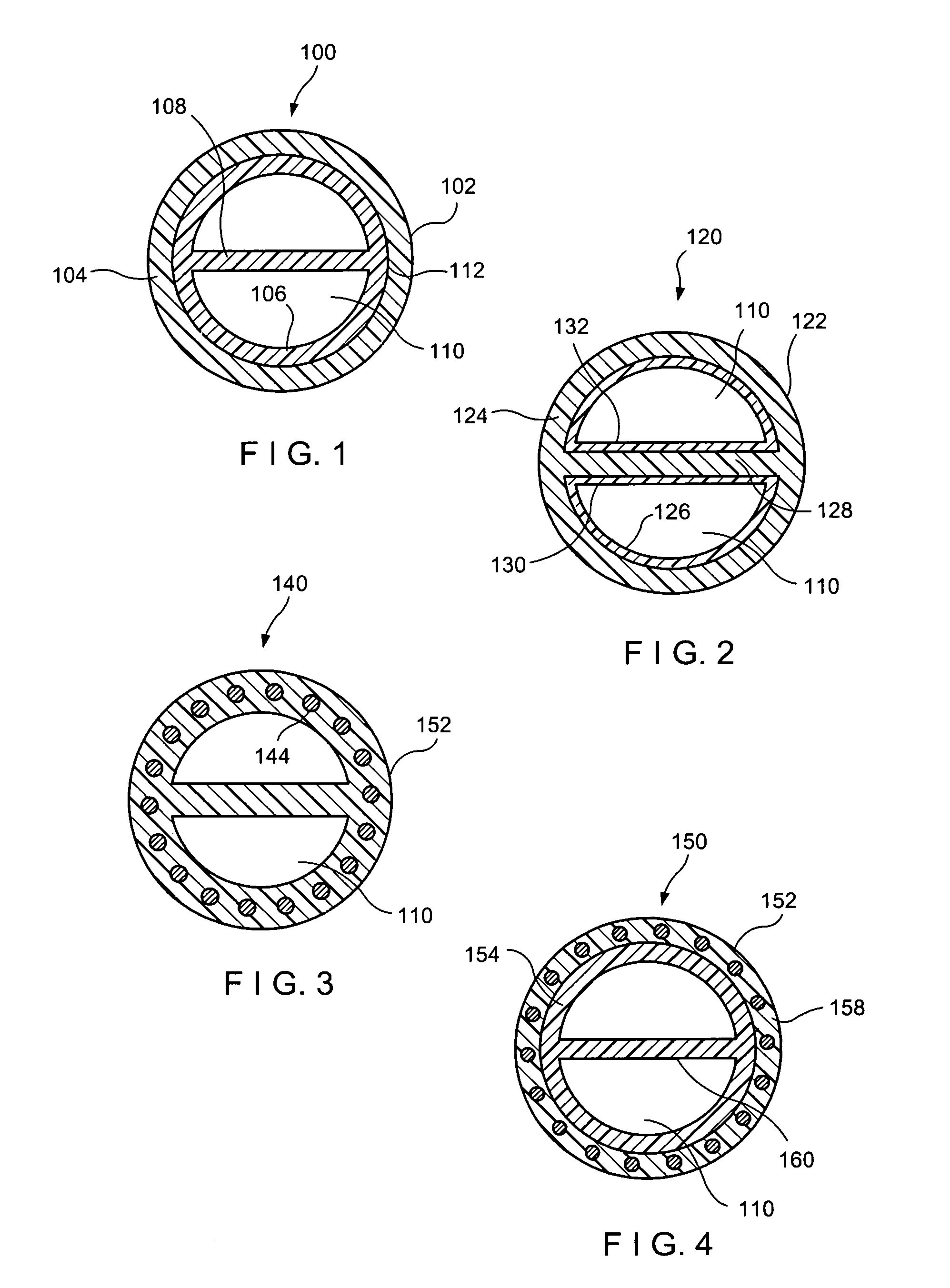
[0014]The present invention may be further understood with reference to the following description and the appended drawings, wherein like elements are referred to with the same reference numerals. The invention is related to medical devices used to introduce a contrast media fluid into a patient, preferably at high pressure and with a large flow rate. Specifically, the devices according to the invention may be used to inject the contrast media using a PICC.

[0015]As described above, where repeated access to the vascular system is required, a semi-permanent central venous catheter may be inserted in a vein kept in place for up to two years. A PICC typically comprises a flexible elongated portion tunneled from a remote peripheral location (an arm or leg) to a location near the heart. The proximal end of the PICC may be accessed via a port placed, for example, subcutaneously in the arm or chest of the patient or which may remain outside of the body.

[0016]As would be understood by those ...


PUM

PropertyMeasurementUnit
flow rateaaaaaaaaaa
burst pressureaaaaaaaaaa
flexibleaaaaaaaaaa

Abstract

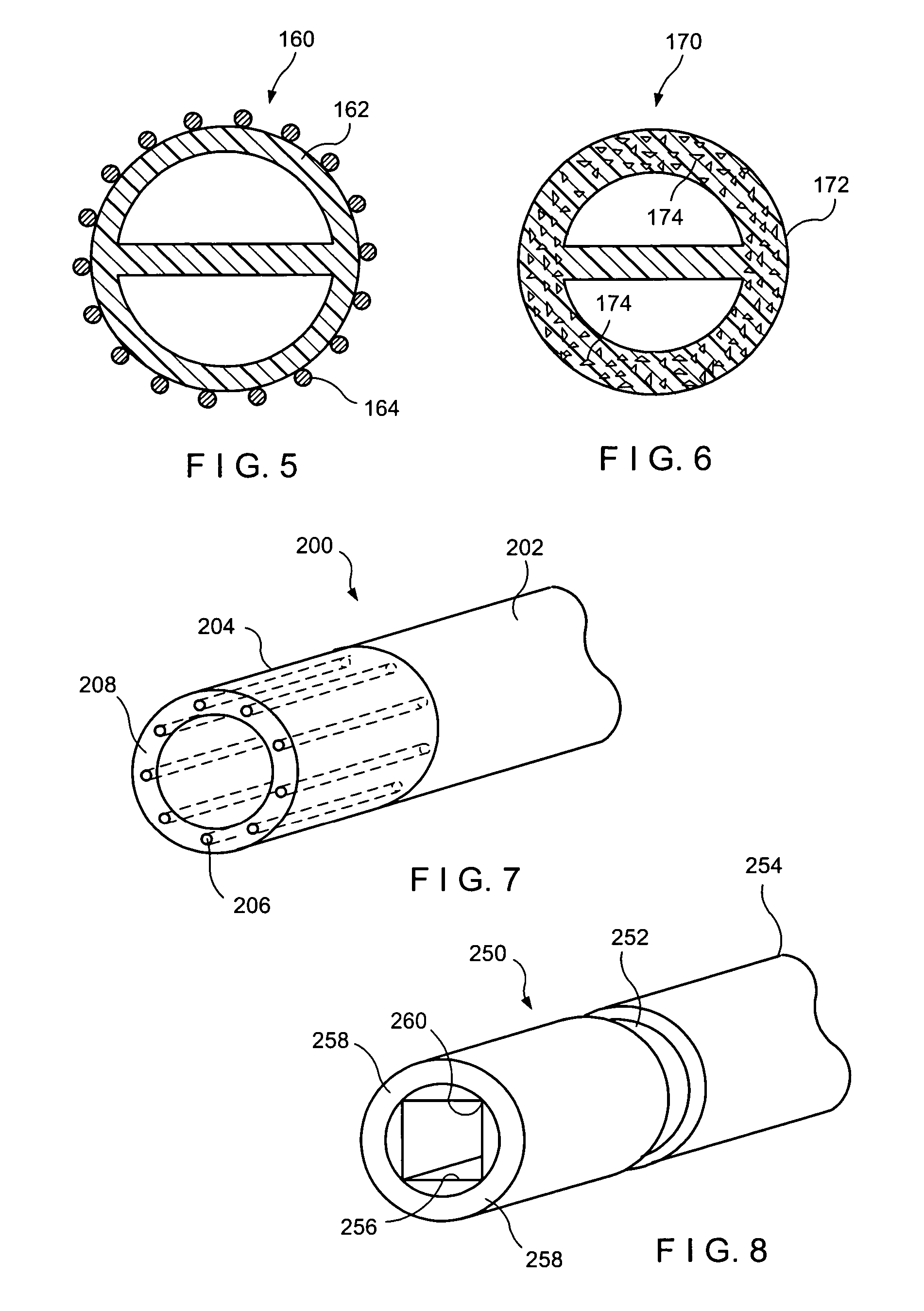
A catheter for medical procedures comprises a shaft portion having a distal end insertable into a body lumen, the shaft portion having a wall defining a working lumen extending therewithin and a first strengthening element coupled to the wall to increase a burst pressure of the shaft portion, wherein the first strengthening element cooperates with a base material of the wall to define a flexible region of the shaft portion allowing the shaft portion to be atraumatically inserted into the body lumen.

Description

BACKGROUND OF THE INVENTION[0001]The treatment of chronic disease often requires repeated and prolonged access to a patient's vascular system to, e.g., to administer medications, blood products, nutrients and other fluids and / or to withdraw blood. When such procedures must be frequently repeated, it may be impractical and / or dangerous to insert and remove the catheter and the needle for each session. In this case, a semi-permanent catheter, (e.g., a peripherally inserted central catheter (PICC)), may be used. As would be understood by those skilled in the art, a PICC is a catheter that is inserted in a vein at a peripheral location, such as the arm or leg and threaded through the vein to the chest, in proximity to the heart.[0002]To simplify the insertion process and reduce patient discomfort, PICCs and other semi-permanent catheters are generally made small and thin. Accordingly, their structural strength is limited by the thickness and type of material forming the catheter's walls...

Claims


Application Information

Patent Timeline
Patent Type & Authority Patents(United States)
IPC IPC(8): A61M25/00
CPCA61M25/0045A61M25/0052A61M25/0069A61M2025/0031A61M2025/0037A61M2025/0059A61M2025/0063
Inventor BELL, BARBARABOURNE, GEORGELAREAU, RAYMONDDIMATTEO, KRISTIAN
Owner ANGIODYNAMICS INC
Learn More