Gravimetric moisture measurement instrument

a gravimetric and moisture content technology, applied in the direction of instruments, weighing by absorbing components, weighing apparatus details, etc., can solve the problems of reducing the accuracy of commercially available instruments, affecting the accuracy of commercial instruments, and affecting etc., to achieve the effect of facilitating the operation of putting samples

Active Publication Date: 2010-12-14
METTLER TOLEDO GMBH
View PDF38 Cites 38 Cited by
  • Summary
  • Abstract
  • Description
  • Claims
  • Application Information

AI Technical Summary

Benefits of technology

[0016]The suction device slightly lowers the pressure level in the test compartment, whereby a gaseous medium is pulled in from outside the measuring instrument, for example through passages in the walls of the test compartment. The gaseous medium is channeled in an appropriate manner through the test compartment where it absorbs the moisture, whereupon it is removed from the test compartment through the suction device. In addition, the slight lowering of the pressure in the test compartment promotes the escape of the moisture from the sample. Of course, the gaseous medium can also be fed through the test compartment under an overpressure.
[0040]By conditioning the test compartment before starting the actual measurement, it is possible to achieve stationary conditions in the test compartment, which improves the reproducibility of the measurement results.

Problems solved by technology

Due to the extensive amount of work involved, this method is very expensive as well as error-prone.
Especially the stringent requirements imposed on the test compartment are setting a limit to the accuracy of the commercially available instruments.
Depending on the sample whose moisture content is to be determined, it is possible that as a result of the heating, other volatile substances are driven out of the sample, which may for example have a strong odor of their own or could be toxic or caustic.
Since this force depends to a large part on the velocity of the air flow in the test compartment, but as it also continuously changes due to the variable conditions in the test compartment, it is very difficult to compensate the error that this force causes in the weighing result.
Due to the errors in the time data which occur as a result, the accuracy that can be achieved in an analysis according to the mathematical model described above is limited.
However, this requires a very long drying time, whereby the risk is increased that a thermal decomposition or oxidation of the sample will occur as a result of the extended exposure to the heat from the radiation source.
For the reasons that have just been explained, it is hardly possible to determine an absolute value for the moisture content with a gravimetric moisture-determination instrument.
This method is very labor-intensive, prone to user errors, and expensive.

Method used


Image

  • Gravimetric moisture measurement instrument
  • Gravimetric moisture measurement instrument
  • Gravimetric moisture measurement instrument

Examples


first embodiment

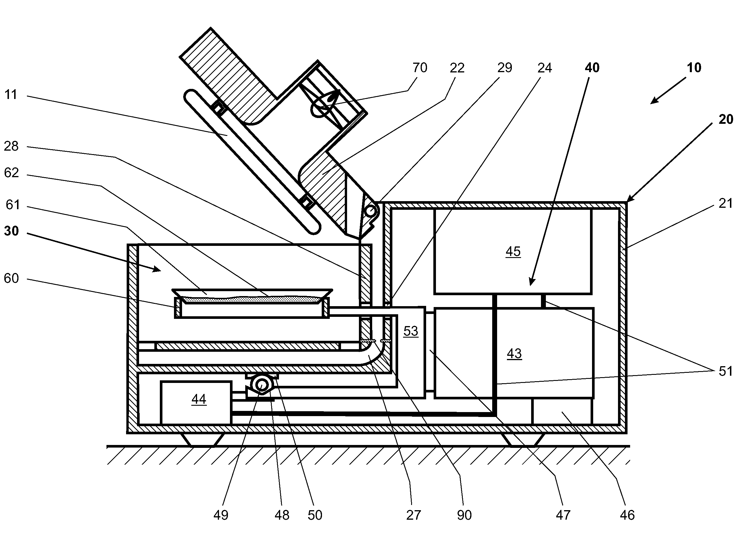
[0077]FIG. 1, in a sectional view, illustrates a measuring instrument 10 in a The measuring instrument 10 has a housing 20 in which a test compartment 30 is arranged. The housing 20 is divided into a movable housing part 22 and a stationary housing part 21. Arranged in the stationary housing part 21 are a weighing cell 43, a calibration-weight-handling mechanism 44, and at least one electronic module 45, all of which are connected to each other by communicating means 51. The electronic module 45 contains at least one signal-processing module that is not shown in detail, and possibly also a control- and / or regulation module. The weighing cell 43 has at least a stationary portion 46 and a load-receiving portion 47. Known types of weighing cells are for example elastically deforming bodies carrying strain gauges, or weighing cells based on the principle of electromagnetic force compensation, or weighing cells with oscillating strings, capacitative weighing sensors and the like. The st...

second embodiment

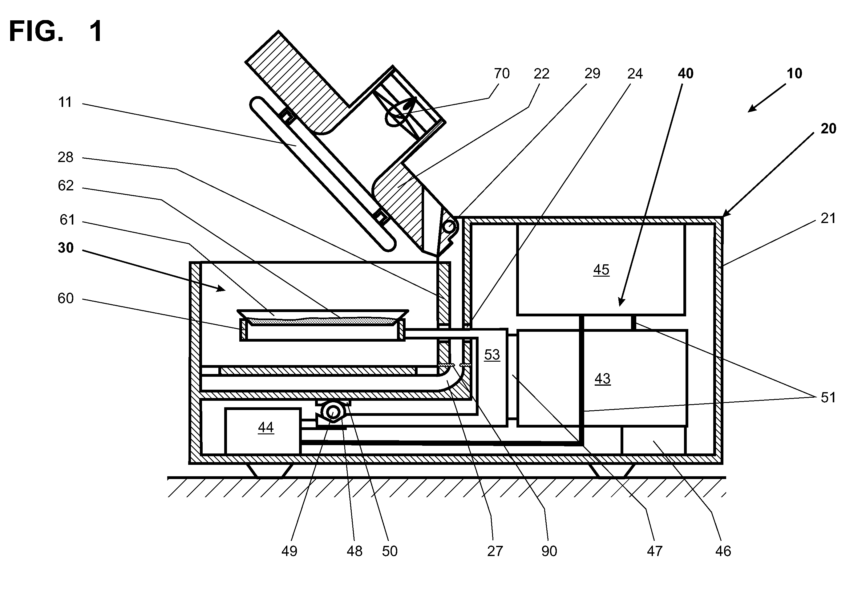
[0082]FIG. 2 shows a cross-sectional view of the measuring instrument 110 according to the invention. The measuring instrument 110 itself is to a large extent analogous to the measuring instrument of FIG. 1. The same reference numerals are used for features that are identical, and the features are not described again in detail. In the test compartment 130 of the measuring instrument 110, which is shown in the closed condition in FIG. 2, an interior draft shield 119 is arranged which partially surrounds the sample receiver 60. Atmospheric currents of the gaseous medium can thereby be prevented from influencing the sample receiver 60. As already mentioned in the description of FIG. 1, the passage 24 is configured as a tubular conduit between the test compartment 130 and an interior space 118 of the stationary housing part 21 in which the weighing device 40 is arranged. The connecting member 53 reaches through this passage opening 124 and connects the sample receiver 60 to the load-rec...

third embodiment

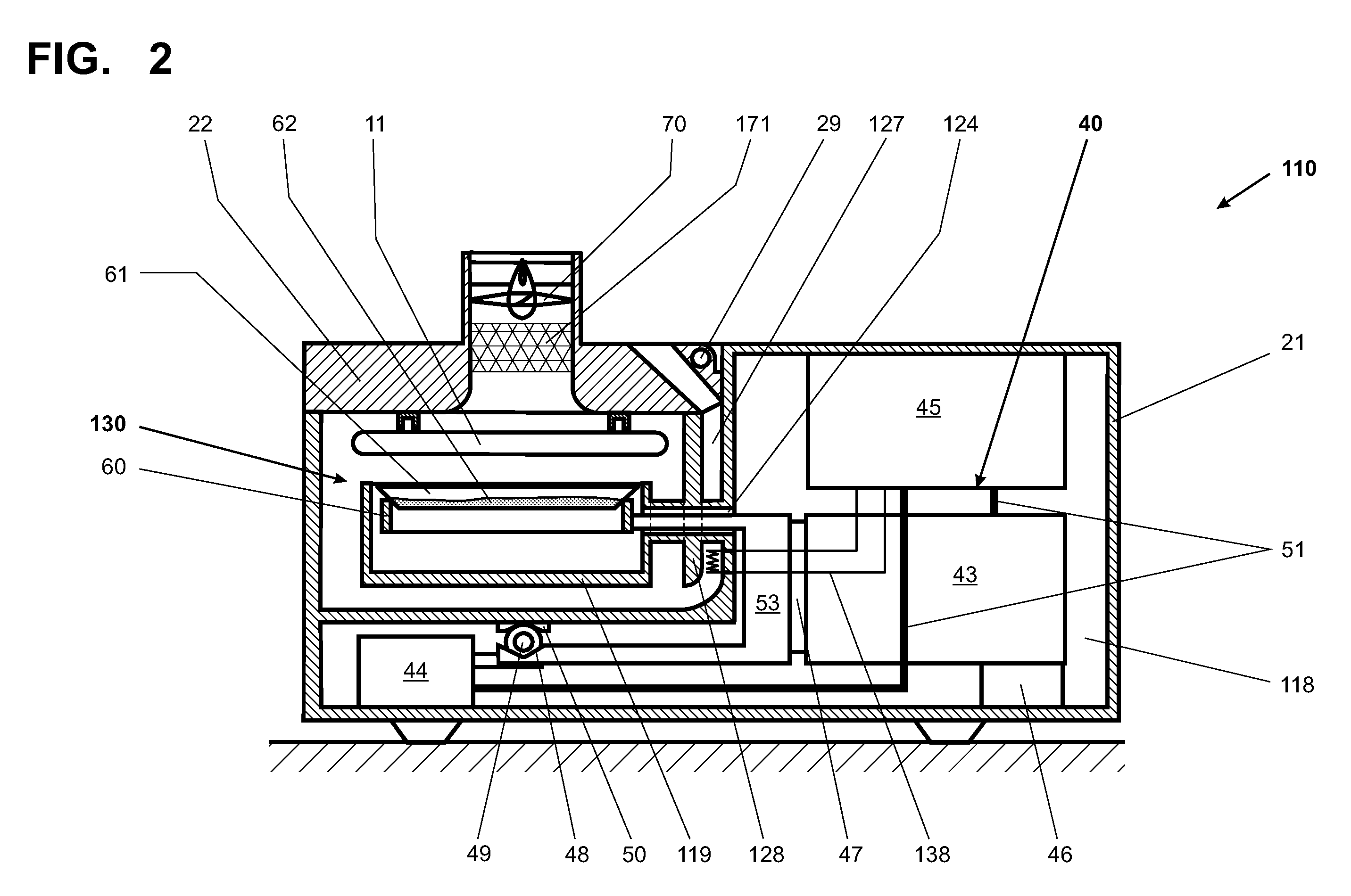
[0083]FIG. 3 represents a cross-sectional view of the measuring instrument 210 in a A weighing device 240 arranged in the housing 220 has substantially the same elements as were named above in the description of FIG. 1 for the weighing device 40. The housing 220 is divided into a stationary housing part 221 and a movable housing part 222.

[0084]The weighing device 240 is largely enclosed by the stationary housing part 221. Only a sample receiver 260 which is connected to the weighing device 240 protrudes from the stationary housing part 221 and reaches into the space of the movable housing part 222 when the latter is set in position for performing measurements. Receptacles of different shapes such as sample trays 262, crucibles and the like can be placed on this sample receiver 260 which is ring-shaped in this example.

[0085]The movable housing part 222 forms the outer envelope of a unit which is pivotally connected to the stationary housing 221 so as to allow the movable housing par...


PUM


Abstract

A measuring instrument for the gravimetric determination of moisture has a housing with a test compartment arranged in the housing, as well as a weighing device installed in the housing. The weighing device includes a sample receiver that is disposed inside the test compartment when in the measuring position. A radiation source arranged in the test compartment which during a test process serves to heat the sample placed on the sample receiver. A suction device, arranged adjacent to the test compartment, remove moisture and any other volatiles given off by the sample during the measurement process providing a more stable flow pattern in the test compartment.

Description

CROSS-REFERENCE TO RELATED APPLICATIONS[0001]This application claims a right of priority under 35 USC §119 from European patent application 06 11 3030.8, filed 25 Apr. 2006, the content of which is incorporated by reference as if fully recited herein.TECHNICAL FIELD[0002]The present invention relates to a measuring instrument for the gravimetric determination of moisture content.BACKGROUND OF THE ART[0003]To determine the moisture content in a sample, the sample is dried and the weight of the sample is measured before and after the drying process. Due to the extensive amount of work involved, this method is very expensive as well as error-prone.[0004]In some cases, the weight loss can also be measured during the drying process. In a given sample, the decrease in weight is a function of the temperature, the length of the drying time, and the conditions in the test compartment, and it conforms to a weight-versus-time curve which asymptotically approaches the dry weight of the sample. ...

Claims


Application Information

Patent Timeline
Patent Type & Authority Patents(United States)
IPC IPC(8): G01G21/28G01G23/48G01G23/01
CPCG01N5/045G01N5/025G01N22/04
Inventor LUCHINGER, PAUL
Owner METTLER TOLEDO GMBH
Why Eureka
Try Eureka