
Data output control circuit of a double data rate (DDR) synchronous semiconductor memory device responsive to a delay locked loop (DLL) clock

a data output control and data rate technology, applied in the field of semiconductor memory devices, can solve the problems of delay amount, insufficient operation margin of 14 period of system clock, and inability of synchronous semiconductor memory devices to meet the required, and achieve the effect of constant operation margin

Active Publication Date: 2010-12-14
SK HYNIX INC
View PDF11 Cites 3 Cited by
  • Summary
  • Abstract
  • Description
  • Claims
  • Application Information

AI Technical Summary

Benefits of technology

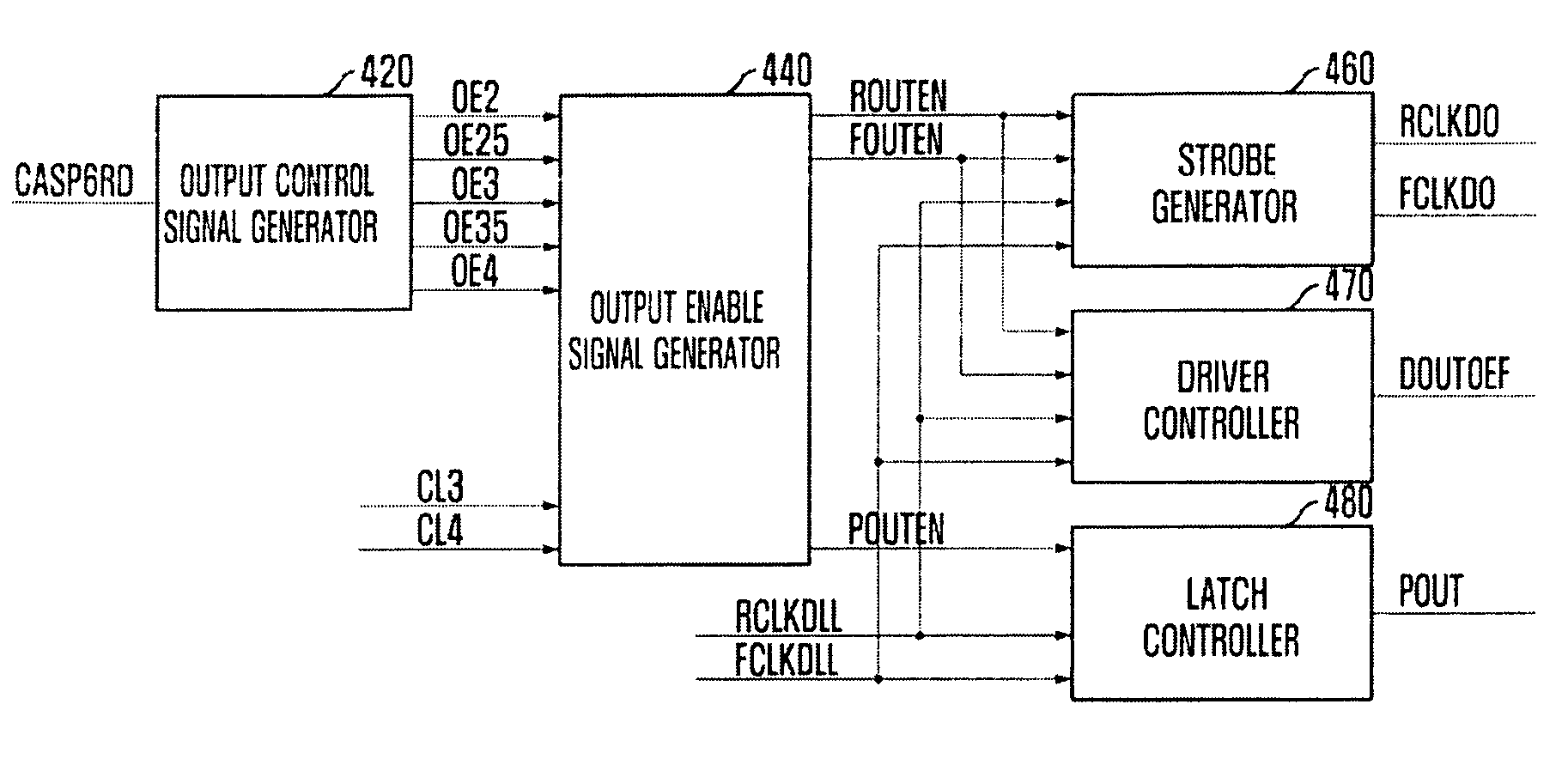
"The present invention provides a semiconductor memory device that uses a high-frequency system clock and maintains a constant operation margin even in changes of operating environment. The invention includes a data output control circuit that generates output source signals corresponding to the rising and falling edges of the system clock and a latch controller that enables a pipeline latch in response to the first rising enable signal and a delay locked loop (DLL) clock. The invention also includes a driver controller that enables a data output driver in response to the second rising enable signal and a strobe generator that outputs rising and falling data output signals. The invention further includes a method of controlling data outputted in synchronization with the falling edge of the system clock using a first output source signal corresponding to the rising edge of the system clock and a second output source signal corresponding to the falling edge of the system clock. The technical effects of the invention include improved operational stability and efficiency of semiconductor memory devices."

Problems solved by technology

However, since even the synchronous semiconductor memory device could not meet the required data input / output speed, a double data rate (DDR) synchronous semiconductor memory device has been developed.
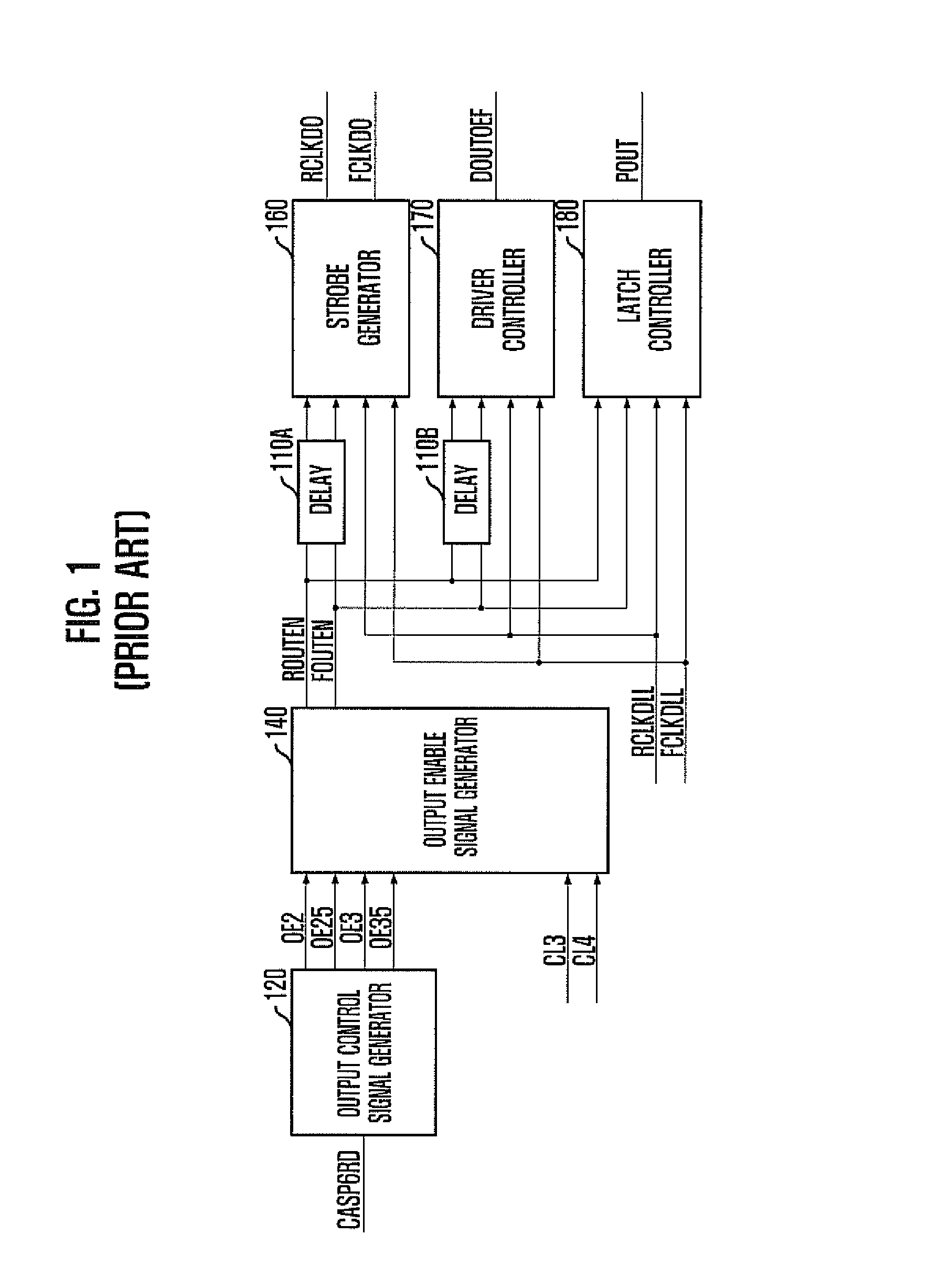
However, due to the change of operating environment of the semiconductor memory device, such as voltage level, temperature, and process, the delay amount of the delays 110A and 110B using a plurality of delay elements may be changed.
Furthermore, when the semiconductor memory device uses a system clock with a high frequency, the operation margin corresponding to ¼ period of the system clock may be insufficient.

Method used


Image

  • Data output control circuit of a double data rate (DDR) synchronous semiconductor memory device responsive to a delay locked loop (DLL) clock
  • Data output control circuit of a double data rate (DDR) synchronous semiconductor memory device responsive to a delay locked loop (DLL) clock
  • Data output control circuit of a double data rate (DDR) synchronous semiconductor memory device responsive to a delay locked loop (DLL) clock

Examples


Embodiment Construction

[0039]Hereinafter, a semiconductor memory device in accordance with the present invention will be described in detail with reference to the accompanying drawings.

[0040]The semiconductor memory device of the invention may include a data output control circuit configured to control data outputted in synchronization with a falling edge of a system clock using a first output source signal synchronized with a rising edge of the system clock, and to control data outputted in synchronization with the rising edge of the system clock using a second output source signal synchronized with a falling edge of the system clock, and a data output circuit (not shown) configured to output data received from the inside to the outside, the data output circuit being controlled by the data output control circuit. Herein, data output circuit may include a pipeline latch configured to temporarily store data for aligning the data outputted from a plurality of unit cells, and an output driver configured to o...


PUM


Abstract

A semiconductor memory device using system clock with a high frequency can maintain a constant margin of operation even with a changed operating environment including voltage level, temperature, and process. The semiconductor memory device includes a data output control circuit configured to control data outputted in synchronization with a falling edge of a system clock using a first output source signal corresponding to a rising edge of the system clock, and to control data outputted in synchronization with the rising edge of the system clock using a second output source signal corresponding to a falling edge of the system clock, and a data output circuit configured to output data, the data output circuit being controlled by the data output control circuit.

Description

CROSS-REFERENCE TO RELATED APPLICATIONS[0001]The present invention claims priority of Korean patent application number 10-2007-0111568, filed on Nov. 2, 2007, which is incorporated by reference in its entirety.BACKGROUND OF THE INVENTION[0002]The present invention relates to a semiconductor memory device, and more particularly to a delay locked loop (DLL) circuit for controlling an internal operation to output data in synchronization with a system clock when an external command is inputted to a semiconductor memory device.[0003]In a system with a variety of semiconductor devices, a semiconductor memory device serves as data storage. The semiconductor memory device outputs data corresponding to addresses received from a data processor, e.g., a central processing unit (CPU), or stores data received from the data processor into memory cells selected by addresses.[0004]As the operating speed of such systems is increasing and semiconductor integrated circuit technologies are advancing, s...

Claims


Application Information

Patent Timeline
Patent Type & Authority Patents(United States)
IPC IPC(8): G11C7/22
CPCG11C7/1051G11C7/1066G11C7/22G11C7/222G11C11/407G11C11/4096
Inventor BYUN, HEE-JIN
Owner SK HYNIX INC
Learn More