Imaging system for imaging an object

a computer program and imaging system technology, applied in applications, instruments, nuclear engineering, etc., can solve problems such as image artefacts, and achieve the effect of improving image quality

Active Publication Date: 2010-12-14
KONINK PHILIPS ELECTRONICS NV
View PDF3 Cites 4 Cited by
  • Summary
  • Abstract
  • Description
  • Claims
  • Application Information

AI Technical Summary

Benefits of technology

[0004]It is an object of the present invention to provide an imaging system, which generates images by using truncated projections, wherein these images comprise less artefacts than images generated by known imaging systems using truncated projections, i.e. which generates images of improved image quality. Furthermore, a corresponding imaging method, a corresponding image generation device and a corresponding image generation method shall be provided.

Problems solved by technology

This leads to image artefacts.

Method used


Image

  • Imaging system for imaging an object
  • Imaging system for imaging an object
  • Imaging system for imaging an object

Examples


Embodiment Construction

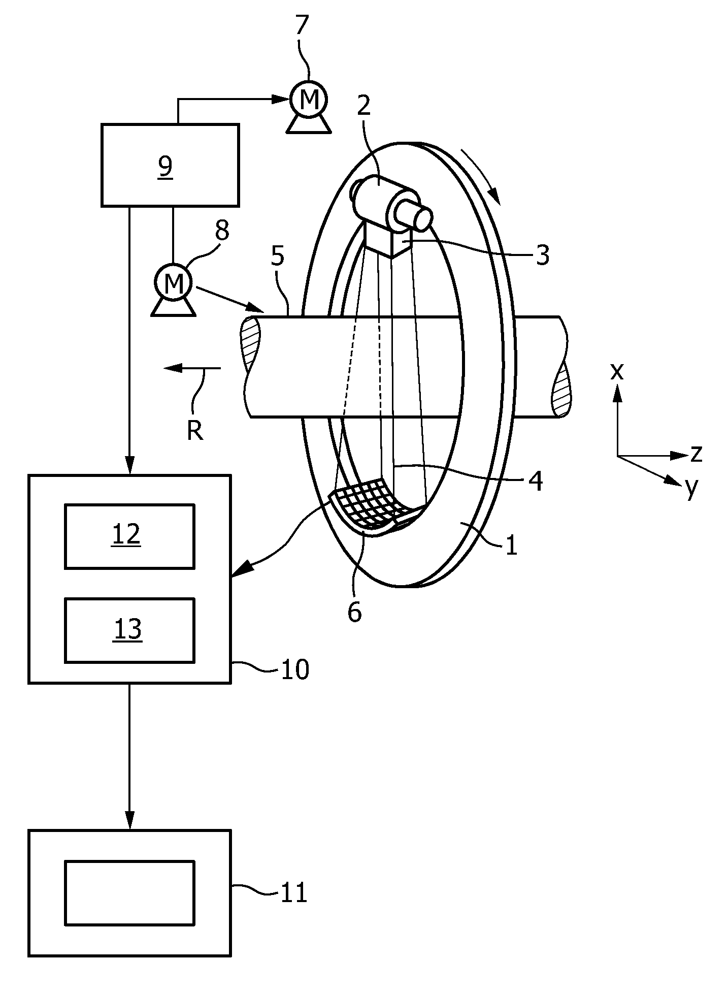
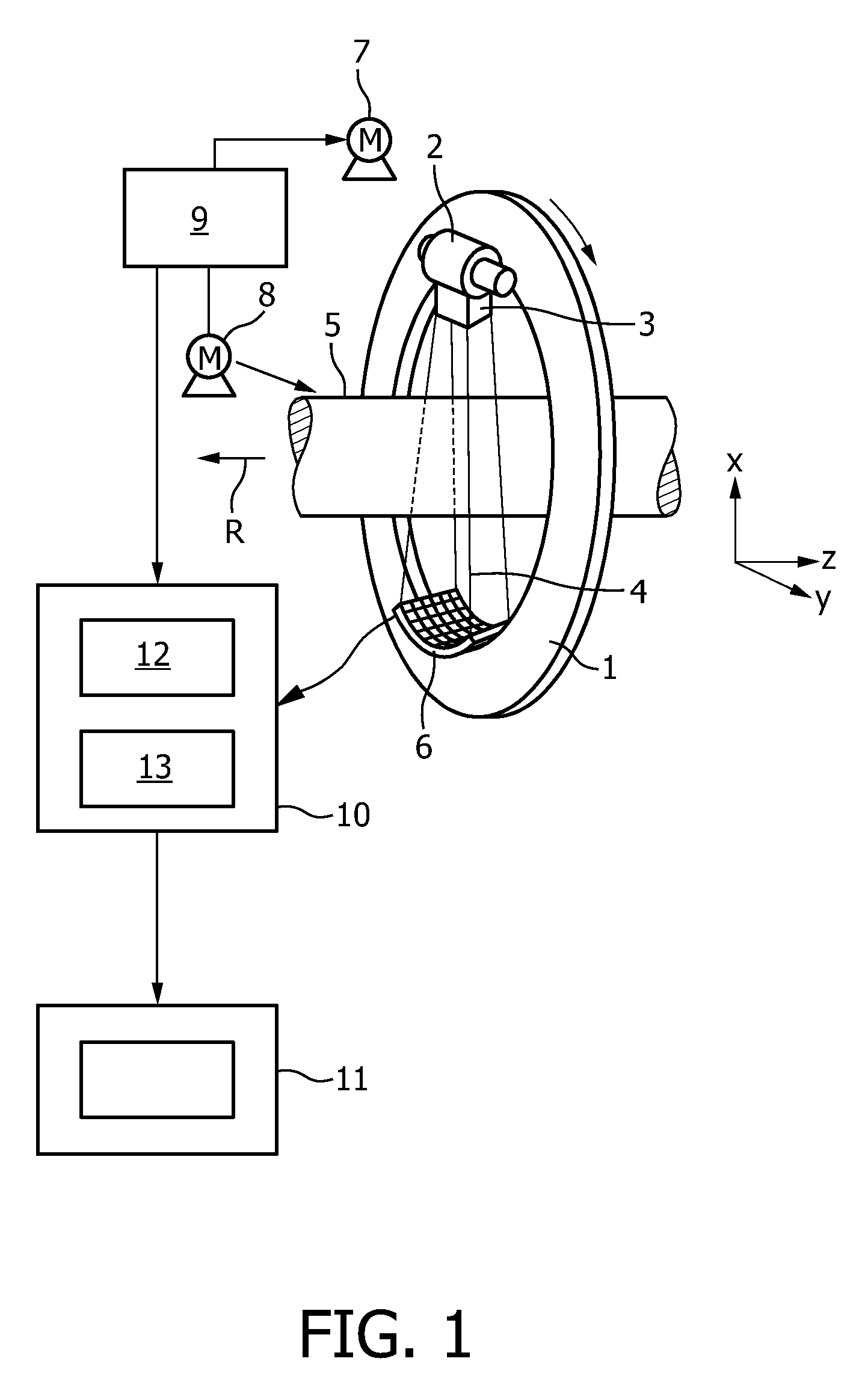
[0033]The imaging system shown in FIG. 1 is a computed tomography system (CT system). The CT system includes a gantry 1 which is capable of rotation about an axis of rotation R which extends parallel to the z direction. The polychromatic radiation source 2, which is in this embodiment an X-ray tube emitting polychromatic X-ray radiation, is mounted on the gantry 1. The X-ray source 2 is provided with a collimator device 3 which forms in this embodiment a conical radiation beam 4 from the radiation produced by the X-ray tube 2. The radiation traverses an object (not shown), such as a patient or vessels of the human heart, in a region of interest in an examination zone 5, which is in this embodiment cylindrical. After having traversed the examination zone 5, the X-ray beam 4 is incident on an energy-resolving radiation detector, which is in this embodiment an energy-resolving X-ray detector unit 6 being a two-dimensional detector mounted an the gantry 1. The imaging system comprises a...


PUM


Abstract

The present invention relates to an imaging system for imaging an object (20) comprising a polychromatic radiation source (2) and an energy resolving radiation detector (6). The imaging system comprises further a driving device for moving the object (20) and the radiation source (2) relatively to each other, in order to acquire truncated projections from different directions. A calculation unit determines a k-edge component at least of one of the object (20) and a substance within the object (20) from the truncated projections and determines non-truncated projections from the determined k-edge component. A reconstruction unit constructs the object using the non-truncated projections.

Description

FIELD OF THE INVENTION[0001]The present invention relates to an imaging system, an imaging method and a computer program for imaging an object. The invention relates further to a corresponding image generation device, image generation method and computer program for generating an image of an object.BACKGROUND OF THE INVENTION[0002]Known imaging systems, which acquire truncated projections of an object, reconstruct an image by using these truncated projections. This leads to image artefacts. These known imaging systems use interpolation techniques in order to generate non-acquired missing data and to complete a truncated projection to obtain a non-truncated projection. These calculated non-truncated projections are only approximations so that an image, which has been reconstructed using these calculated non-truncated projections, comprises artefacts.[0003]In “Efficient correction for CT image artefacts caused by objects extending outside the scan field of view”, B. Ohnesorge, T. Floh...

Claims


Application Information

Patent Timeline
Patent Type & Authority Patents(United States)
IPC IPC(8): A61B6/00
CPCG01T1/2985A61B6/4241A61B6/482Y10S378/901
Inventor PROKSA, ROLAND
Owner KONINK PHILIPS ELECTRONICS NV
Why Eureka
Try Eureka