
Authenticity verification methods, products and apparatuses

a verification method and verification method technology, applied in the field of security methods, can solve problems such as inability to make an idea work properly, difficulty may be imposed, and criminals becoming more sophisticated

Inactive Publication Date: 2010-12-14
INGENIA HLDG LTD
View PDF251 Cites 82 Cited by
  • Summary
  • Abstract
  • Description
  • Claims
  • Application Information

AI Technical Summary

Benefits of technology

[0018]It has thus been discovered that it is possible to gain all the advantages of speckle based techniques without having to use a specially prepared token or specially prepare an article in any other way. In particular, many types of paper and cardboard have been found to give unique characteristic scattering signals from a coherent light beam, so that unique digital signatures can be obtained from almost any paper document or cardboard packaging item.
[0029]Although a working reader can be made with only one detector channel, there are preferably at least 2 channels. This allows cross-correlations between the detector signals to be made, which is useful for the signal processing associated with determining the signature. It is envisaged that between 2 and 10 detector channels will be suitable for most applications with 2 to 4 currently being considered as the optimum balance between apparatus simplicity and security.
[0035]It can therefore be advantageous to mount the source so as to direct the coherent beam onto the reading volume so that it will strike an article with near normal incidence. By near normal incidence means ±5, 10 or 20 degrees. Alternatively, the beam can be directed to have oblique incidence on the articles. This will usually have a negative influence in the case that the beam is scanned over the article.

Problems solved by technology

Many traditional authentication security systems rely on a process which is difficult for anybody other than the manufacturer to perform, where the difficulty may be imposed by expense of capital equipment, complexity of technical know-how or preferably both.
Unfortunately, criminals are becoming more sophisticated and can reproduce virtually anything that original manufacturers can do.
However, Kralovec reports that this idea could not be made to work properly, because the optical fibres were too fragile and the speckle pattern changed rapidly when the banknote was circulated owing to wear.
This meant that the speckle pattern measured from the optical fibres in a used banknote no longer matched the barcode, so the banknote could no longer be authenticated from the speckle pattern in the intended manner.
Particularly, integration of a resin token or a magnetic chip in paper or cardboard is not easy and involves significant cost.
Additionally, there is also an inherent security risk of an attachable token-based approach in that the token is potentially detachable and attachable to a different article.
However, their intrinsic security is low.
For example they are vulnerable to fraudulent access to the stored image data which may allow fabrication of an article that could be verified incorrectly as being authentic, or to forging by simply using a high resolution printer to print an image of what would be seen under a microscope when viewing the relevant part of the genuine article.
The security level of direct imaging techniques also scales with the volume of the image data, forcing use of expensive high resolution imaging equipment for higher security levels.
This may be acceptable in some applications, such as postal sorting or banknote verification, but in many applications will be unacceptable.

Method used


Image

  • Authenticity verification methods, products and apparatuses
  • Authenticity verification methods, products and apparatuses
  • Authenticity verification methods, products and apparatuses

Examples


Embodiment Construction

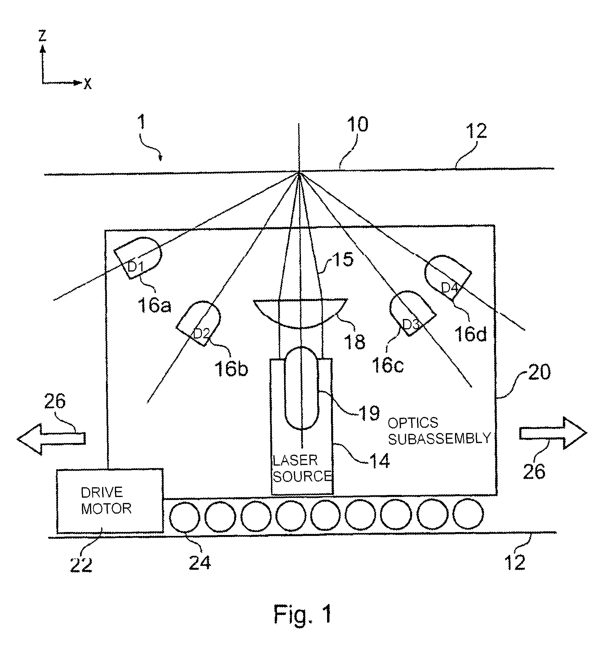
[0092]FIG. 1 is a schematic side view of a reader apparatus 1 embodying the invention. The optical reader apparatus 1 is for measuring a signature from an article (not shown) arranged in a reading volume of the apparatus. The reading volume is formed by a reading aperture 10 which is a slit in a housing 12. The housing 12 contains the main optical components of the apparatus. The slit has its major extent in the x direction (see inset axes in the drawing). The principal optical components are a laser source 14 for generating a coherent laser beam 15 and a detector arrangement 16 made up of a plurality of k photodetector elements, where k=4 in this example, labelled 16a, 16b, 16c and 16d. The laser beam 15 is focused by a cylindrical lens 18 into an elongate focus extending in the y direction (perpendicular to the plane of the drawing) and lying in the plane of the reading aperture. In an example prototype reader, the elongate focus has a major axis dimension of about 2 mm and a mino...


PUM


Abstract

A method and apparatus for determining a digital signature from an article made of paper, cardboard, plastic or many other material types. A coherent light source directs a beam to illuminate the article and a detector arrangement collects data points from light scattered from many different parts of the article to collect a large number of independent data points, typically 500 or more. By collecting a large number of independent signal contributions specific to many different parts of the article, a digital signature can be computed that is unique to the area of the article that has been scanned. This measurement can be repeated whenever required to test authenticity of the article. Using this method, it has been discovered that it is essentially pointless to go to the effort and expense of making specially prepared tokens, since unique characteristics are measurable a in a straightforward manner from a wide variety of every day articles.

Description

[0001]This application is a National Stage of International Application No. PCT / GB2005 / 000922, filed Mar. 9, 2005, which claims priority to (i) Great Britain Patent Application No. 0405641.2, filed Mar. 12, 2004; (ii) U.S. Provisional Application No. 60 / 601,463, filed Aug. 13, 2004; (iii) U.S. Provisional Application No. 60 / 610,075 filed Sep. 15, 2004; and (iv) Great Britain Patent Application No. 0420524.1, filed Sep. 15, 2004.BACKGROUND OF THE INVENTION[0002]The invention relates to security methods, more especially verification of authenticity of an article such as an personal identification (ID) card, vendable product, important document or other item.[0003]Many traditional authentication security systems rely on a process which is difficult for anybody other than the manufacturer to perform, where the difficulty may be imposed by expense of capital equipment, complexity of technical know-how or preferably both. Examples are the provision of a watermark in bank notes and a holog...

Claims


Application Information

Patent Timeline
Patent Type & Authority Patents(United States)
IPC IPC(8): H04L9/32B41M3/14G06K5/00G06K7/10G06K7/14G06K19/06G06K19/067G06K19/14G06V10/145G06V10/44G07D7/00G07D7/12G07D7/20G07F7/08
CPCG06K7/10762G06K7/14G06K9/00577G06K9/2036G06K9/4604G06K19/14G07D7/0026G07D7/0033G07D7/0093G07D7/121G07D7/20G01N21/84B41M3/14G07D7/0043G07D7/0047G07D7/01B42D25/305B42D25/318G06V20/80G06V10/145G06V10/44
Inventor COWBURN, RUSSELL PAUL
Owner INGENIA HLDG LTD
Learn More