
Method and device for referencing the position of an actuating element

a technology of actuating elements and reference positions, which is applied in the direction of mechanical actuating clutches, instruments, mechanical apparatus, etc., can solve the problems of incorrect identification of blockages as reference positions in transmission paths, hazardous operating conditions, etc., and achieve the effect of increasing the safety of referencing positions

Inactive Publication Date: 2010-12-21
SCHAEFFLER TECH AG & CO KG
View PDF16 Cites 5 Cited by
  • Summary
  • Abstract
  • Description
  • Claims
  • Application Information

AI Technical Summary

Benefits of technology

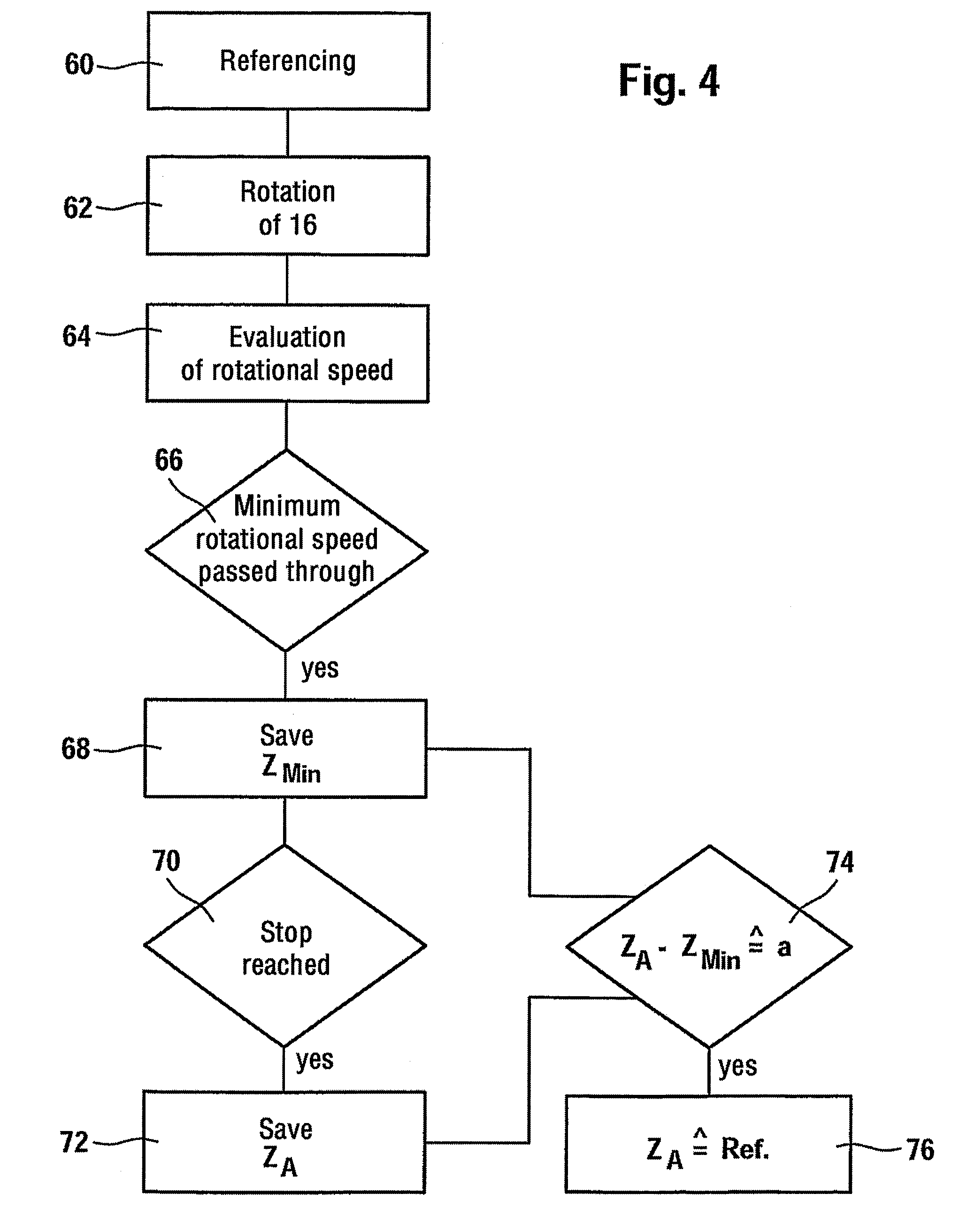
The present invention provides a method and device for increasing the safety of referencing the position of an actuating element of a functional unit, especially a clutch in the drivetrain of a motor vehicle. The method involves checking the position of the actuating element by detecting changes in a variable that occurs when the actuating element reaches a predetermined distance from its reference position. The variable can be the actuation force required to position the actuating element or the speed of the actuating element. The method also includes evaluating the plausibility position of the actuating element and the reference position of the actuating element to increase overall reliability. The device includes an actuator, an incremental sensor, a referencing device, a plausibility device, a control unit, and a comparator to compare the actual plausibility position with the target plausibility position and save the counts of the incremental sensor as valid if the actual plausibility position deviates from the target plausibility position by less than a predetermined value. The invention can be used in various functional units of a motor vehicle.

Problems solved by technology

With referencing that uses stops and thereby recognizes that the actuating element does not move despite the force exerted by the actuator on the actuating element, there is a danger of incorrectly identifying a blockage as a reference position in a transmission path in which the actuating element is located.
Particularly when actuating clutches, this can cause hazardous operating conditions since the vehicle may for example unintentionally drive away.

Method used


Image

  • Method and device for referencing the position of an actuating element
  • Method and device for referencing the position of an actuating element
  • Method and device for referencing the position of an actuating element

Examples


Embodiment Construction

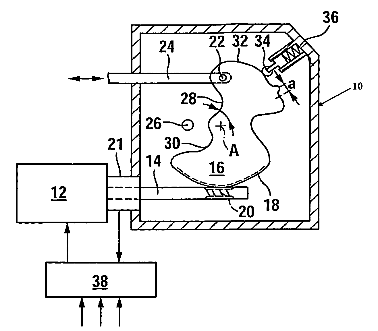
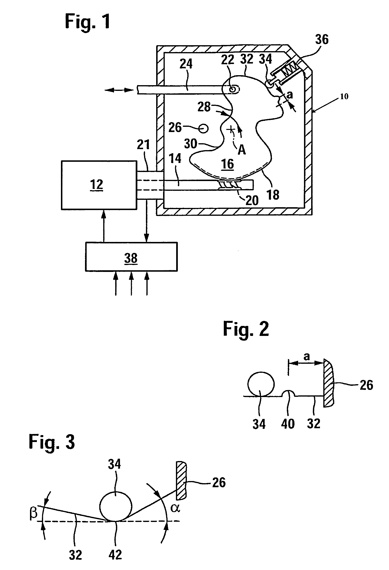
[0026]In FIG. 1, an electric motor 12 is mounted to the housing 10 of a clutch actuation unit, and the output shaft 14 of the electric motor rotatably drives a segment gear 16 rotatably mounted in the housing 10 on an axis A. The segment gear 16 has a peripheral area with teeth 18 that meshes with the helical teeth 20 of the output shaft 14. The rotary position of the output shaft 14 is detected by an incremental sensor 21.

[0027]An operation rod 24 is mounted in a bearing 22 to the segment gear 16, and the movement of the operation rod that can be a linear movement by means of the articulated subdivision of the operation rod is transferred to a release lever of a clutch with a generally known construction. The operation rod 24 can be directly connected to the clutch lever, or for example be connected to the clutch lever by means of a hydraulic transmission path. The rotatability of the segment gear 16 on axis A is limited by a stop 26 fixed to the housing that, in one or the other e...


PUM


Abstract

In a method for referencing the position of an actuating element of a functional unit, in particular of a clutch in the drivetrain of a vehicle, the attainment of a reference position of the actuating element is assessed for plausibility in that it is checked whether a variable which can be applied to the actuating element varies in a predetermined way in a predetermined spacing of the position of the actuating element from the reference position.

Description

[0001]This application is a continuation of prior International Application PCT / DE2007 / 000124, filed Jan. 25, 2007, which is hereby incorporated by reference herein.[0002]The invention relates to a method and device for referencing the position of an actuating element of a functional unit, especially a clutch in the drivetrain of a motor vehicle.BACKGROUND[0003]In the motorized actuation of functional units using an actuating element in which the function of the functional unit changes, e.g., in proportion to the position of the actuating element, it is frequently necessary to reference the position of the actuating element so that the precise position of the actuating element is known in a control unit. An example of this is the motorized actuation of a clutch in which the position of a clutch lever determines the torque transferability of the clutch. A precise knowledge of the torque transferability of the clutch is important to precisely control or regulate starting and shifting....

Claims


Application Information

Patent Timeline
Patent Type & Authority Patents(United States)
IPC IPC(8): G01M13/02
CPCF16D21/06F16D23/12F16D28/00F16D48/064F16D2021/0607F16D2021/0615F16D2021/0684F16D2500/302F16D2500/3026F16D2500/30401F16D2500/5018F16D2500/70605F16D48/00F16D48/06
Inventor PANZER, MATTHIASBAEHR, MARKUSEICH, JUERGENRENFER, ALEXANDERHIRT, JOACHIMWEBER, THOMAS
Owner SCHAEFFLER TECH AG & CO KG
Learn More