
Method for controlling a holding force against, and limiting impact with travel limit positions

a technology of holding force and position, applied in the direction of dynamo-electric converter control, program control, motor/generator/converter stopper, etc., can solve the problem of excessive current situation, overheating the motor and possibly damage, and the precision needed to contact the mechanical travel limi

Active Publication Date: 2010-12-21
DELPHI TECH IP LTD
View PDF8 Cites 12 Cited by
  • Summary
  • Abstract
  • Description
  • Claims
  • Application Information

AI Technical Summary

Benefits of technology

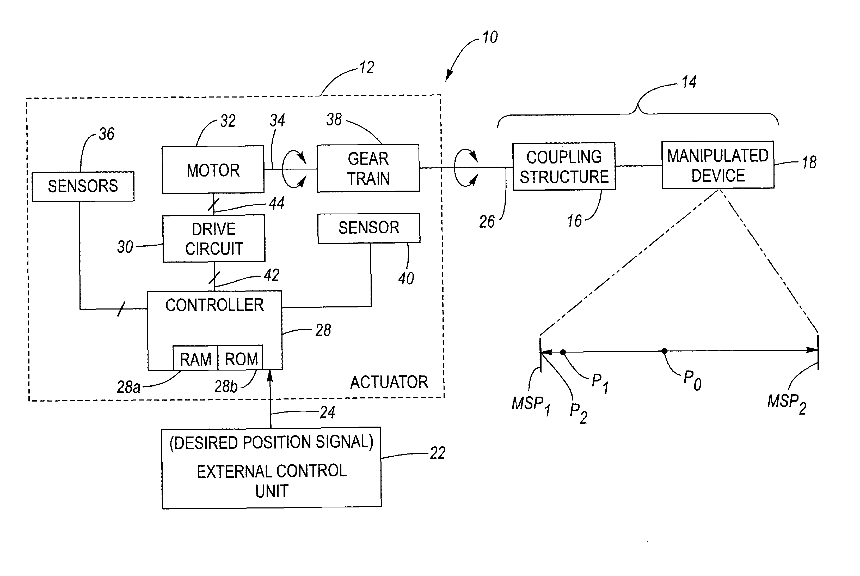
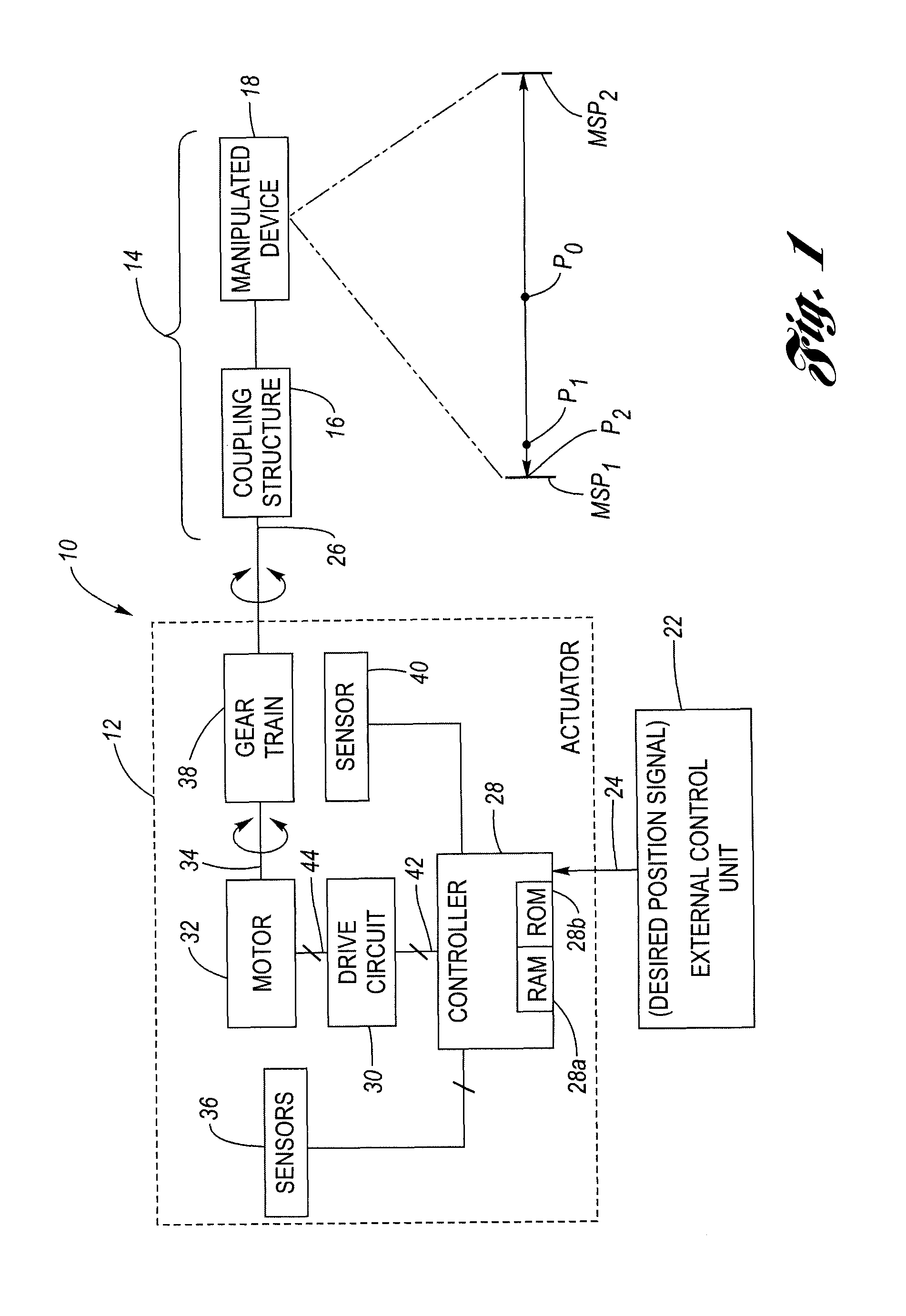
[0005]The present invention provides a method of controlling the operation of a motor-based actuator so as to achieve over-temperature protection when the actuator is causing the manipulated device to apply a force (“push”) against one of the mechanical stops (“travel limits”).
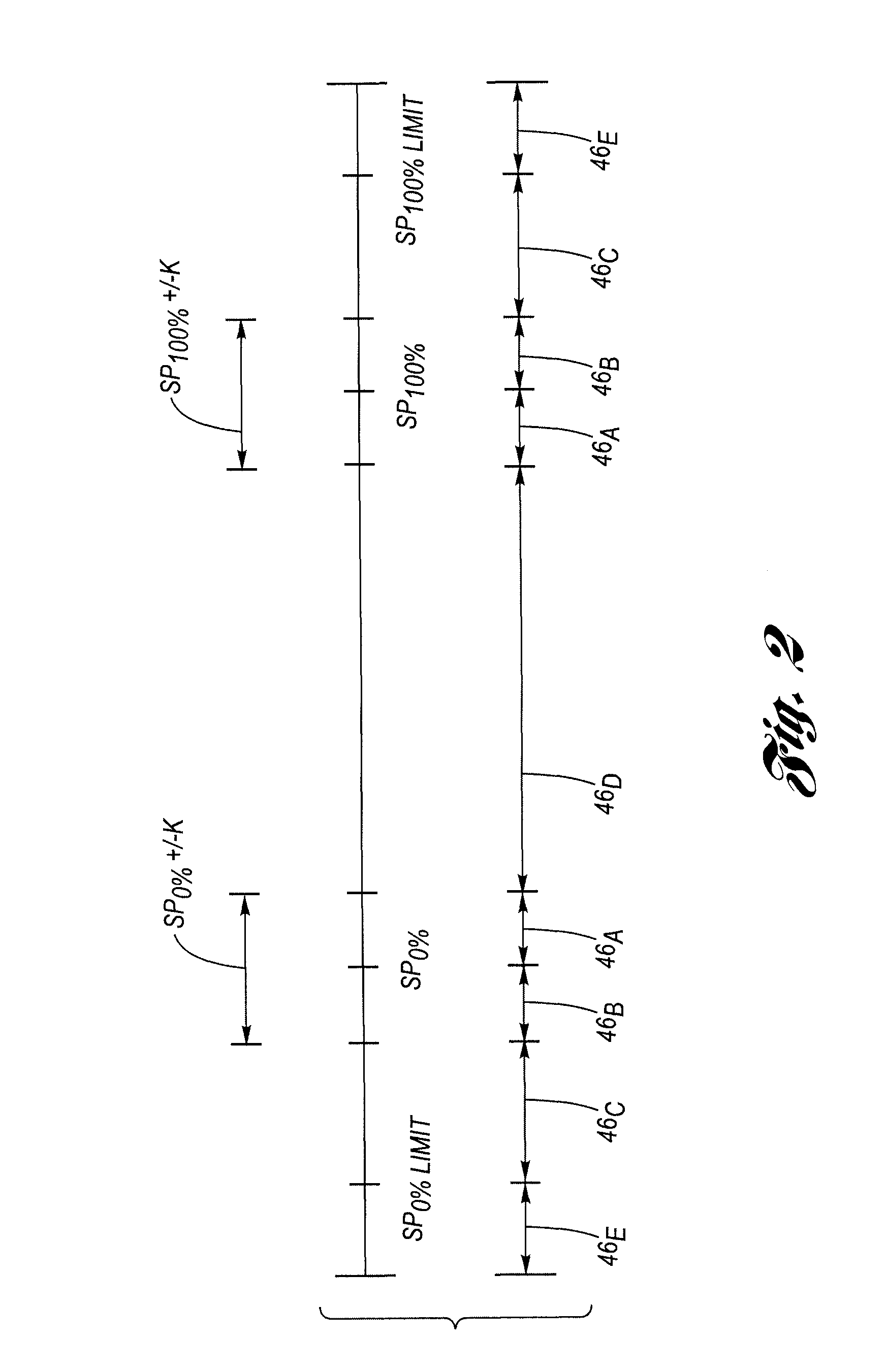
[0007]The method also provides a mechanism for an external control unit to encode in its desired position command to the actuator, a request for one of a plurality of positioning modes. This mechanism allows the actuator to distinguish between an external request to cause the manipulated device to push against one of mechanical stops, on the one hand, versus an external request to simply position the manipulated device at one of the mechanical without applying a force (“pushing”).
[0008]In another aspect of the present invention, a method of operating the actuator is provided that minimizes or eliminates excessive impact of the manipulated device against the mechanical stops due to rotational inertia built up when responding to relatively large changes in the commanded position that takes the manipulated device into the stop.

Problems solved by technology

However, for other applications, such as an EGR valve application, the precision needed required that the mechanical travel limits sometimes be contacted, perhaps for indefinite periods of time.
A problem with contacting the mechanical travel limits, especially for extended periods of time, is that the phase currents provided to the motor would overheat the motor and perhaps damage it.
However, in a stall condition, as would exist when contacting a travel limit, only the resistance of the coils themselves (generally low) impedes current flow, which can result in an excessive current situation.
It is this excessive current that produces undesirable amounts of heat—potentially damaging the motor and / or associated packaging / components.

Method used


Image

  • Method for controlling a holding force against, and limiting impact with travel limit positions
  • Method for controlling a holding force against, and limiting impact with travel limit positions
  • Method for controlling a holding force against, and limiting impact with travel limit positions

Examples


example

[0042]To extend the example previously given, the second commanded device position (source) will be in the range of between (0) to (1000) and the commanded actuator position (target) will be in the range of between (330) to (670) (in motor step counts). This may be mapped directly through a linear transformation, in which (50) maps to (330) and (950) maps to (670), and the intermediate values are linearly mapped. This equates roughly to (900) units in the source being translated to (340) units in the target, or about 3 units on the input range for every unit in the target range. Note, that values lower than (50) or higher than (950) are respectively translated to target values outside of or beyond the learned stops. In this way, requests to push against a stop can be made via such values lower than (50) or higher than (950). Once this relationship has been established, it is straightforward to translate the second (post Table 1) commanded device position into a commanded actuator po...


PUM


Abstract

An actuator includes a motor operated by a controller through a pulse width modulation drive signal applied to a drive circuit that drives the motor. The actuator has an output shaft connected to a coupling structure for manipulating a device such as a variable geometry turbine (VGT) or an exhaust gas recirculation (EGR) valve. The device has a range of motion limited by first and second mechanical stops located at opposing low and high ends of the range. The controller learns the location of the mechanical stops during calibration. An external control unit transmits a desired position to the actuator. A protocol allows the external control unit to implicitly request a positioning mode by virtue of what value range the desired position falls into. The controller is configured to limit the drive signal to a non-harmful level when one of the positioning modes calls for pushing the device against one of the stops.

Description

TECHNICAL FIELD[0001]This invention relates generally to a method for operating an actuator, and more particularly to a method for controlling a holding force against travel limit positions.BACKGROUND OF THE INVENTION[0002]It is known to provide a so-called Smart Remote Actuator (SRA), which is an electro-mechanical device that is configured to actuate or manipulate an attached device, such as for example an engine feature like a position of a variable geometry turbocharger (VGT) or a position of an exhaust gas recirculation (EGR) valve. In one construction, the SRA includes a brushless direct current (BLDC) motor, whose rotor is coupled to a gear-train, which in turn is coupled to an output shaft. The output shaft of the SRA is configured to be coupled by way of intermediate linkage such as a second gear train or a lever-connecting rod-lever combination or the like to transfer the rotation of the output shaft to a desired movement of the manipulated device (e.g., rotation of an EGR...

Claims


Application Information

Patent Timeline
Patent Type & Authority Patents(United States)
IPC IPC(8): G05D3/00
CPCG05B19/4062G05B2219/36464G05B2219/42282G05B2219/43058
Inventor SANDERS, STEPHEN P.CARSEY, JOYCE D.HAZELTON, LAWRENCE D.LANG, JOSJACQUOT, FREDERICNEWMAN, THOMAS W.
Owner DELPHI TECH IP LTD
Learn More