
Video quality assessment

a video quality and video technology, applied in the field of video quality assessment, can solve the problems of inability to accurately estimate the perceived quality degradation of the video packet payload, the inability to take the effect of packet loss into account, and the more likely to suffer from a loss of packets, etc., to achieve the effect of more impact and quality of decoded video

Active Publication Date: 2010-11-30
PSYTECHNICS
View PDF16 Cites 1 Cited by
  • Summary
  • Abstract
  • Description
  • Claims
  • Application Information

AI Technical Summary

Benefits of technology

"The present invention provides a method for estimating the quality of video perceived by a viewer due to packet loss. The method uses a parameter that is calculated based on the number of packets in frames that have been received with one or more lost packets. The method is unaffected by most encryption schemes and can be optimised to maximize the accuracy of the prediction for a particular video endpoint. The parameter takes into account the size of frames affected by packet loss and the position of lost packets within a frame. The weighting coefficients enable the parameter to be optimised to best reflect the behavior of a particular video endpoint. The invention also includes a method for isolating each of the two sub-parameters."

Problems solved by technology

It is suggested that this is due to the fact that as the video coding bit-rate increases, the data from each frame occupies a larger number of packets and is therefore more likely to suffer from a lost packet.
However, this document does not propose a method to take the effect of packet loss on video quality into account.
However, some of these inputs require access to the video payload, such as the number of slices per packet, and many effects are not taken into account, including frame type, the position of packet loss within a frame and the behaviour of the video endpoint.
A key limitation of the quality prediction methods described in the prior art is that in order to take into account the factors listed in the problem statement they require access to elements of the video packet payload.
In such cases, the payload of the video packets cannot be used to make an accurate estimation of the perceived quality degradation due to packet loss.

Method used

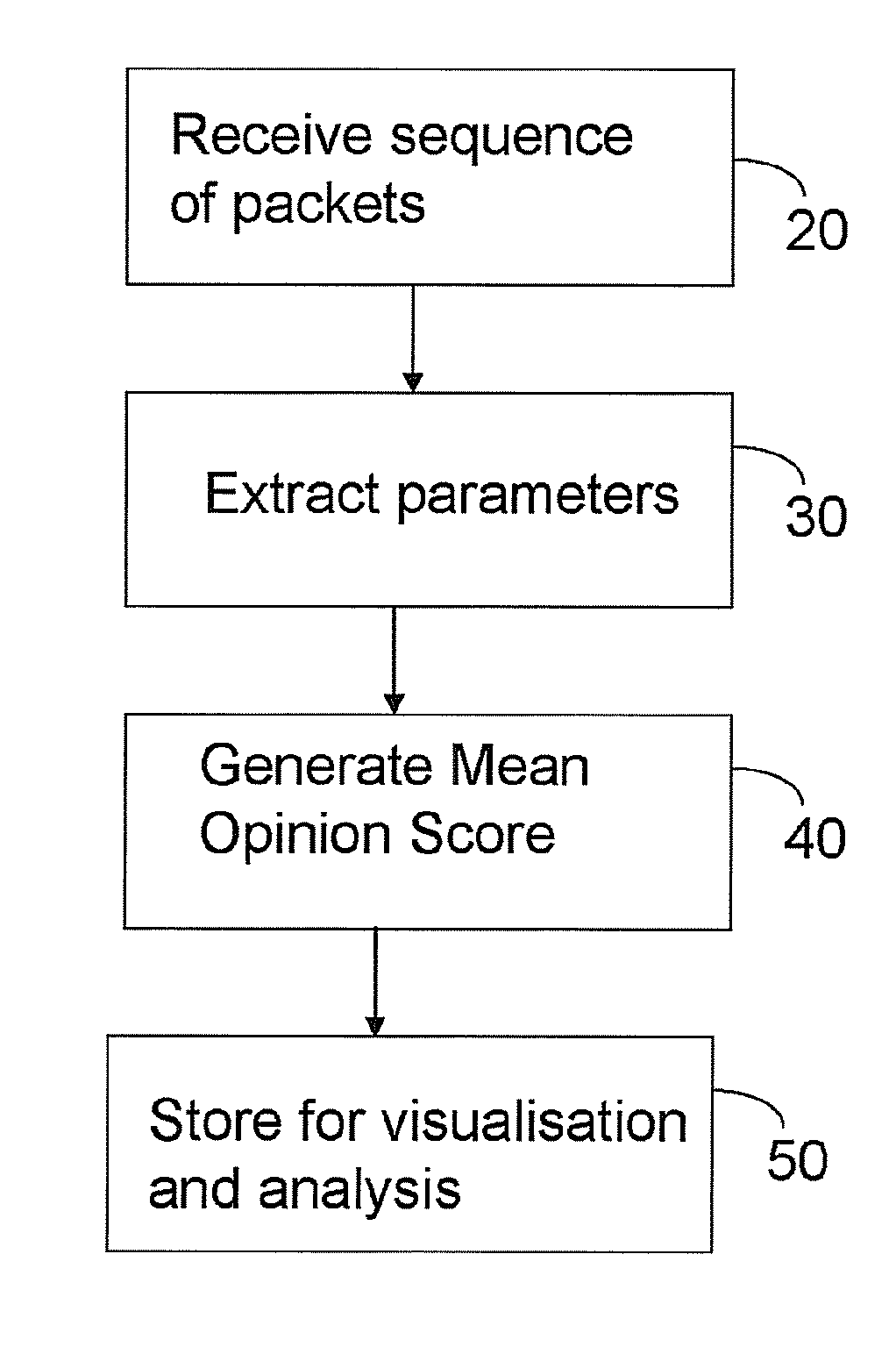
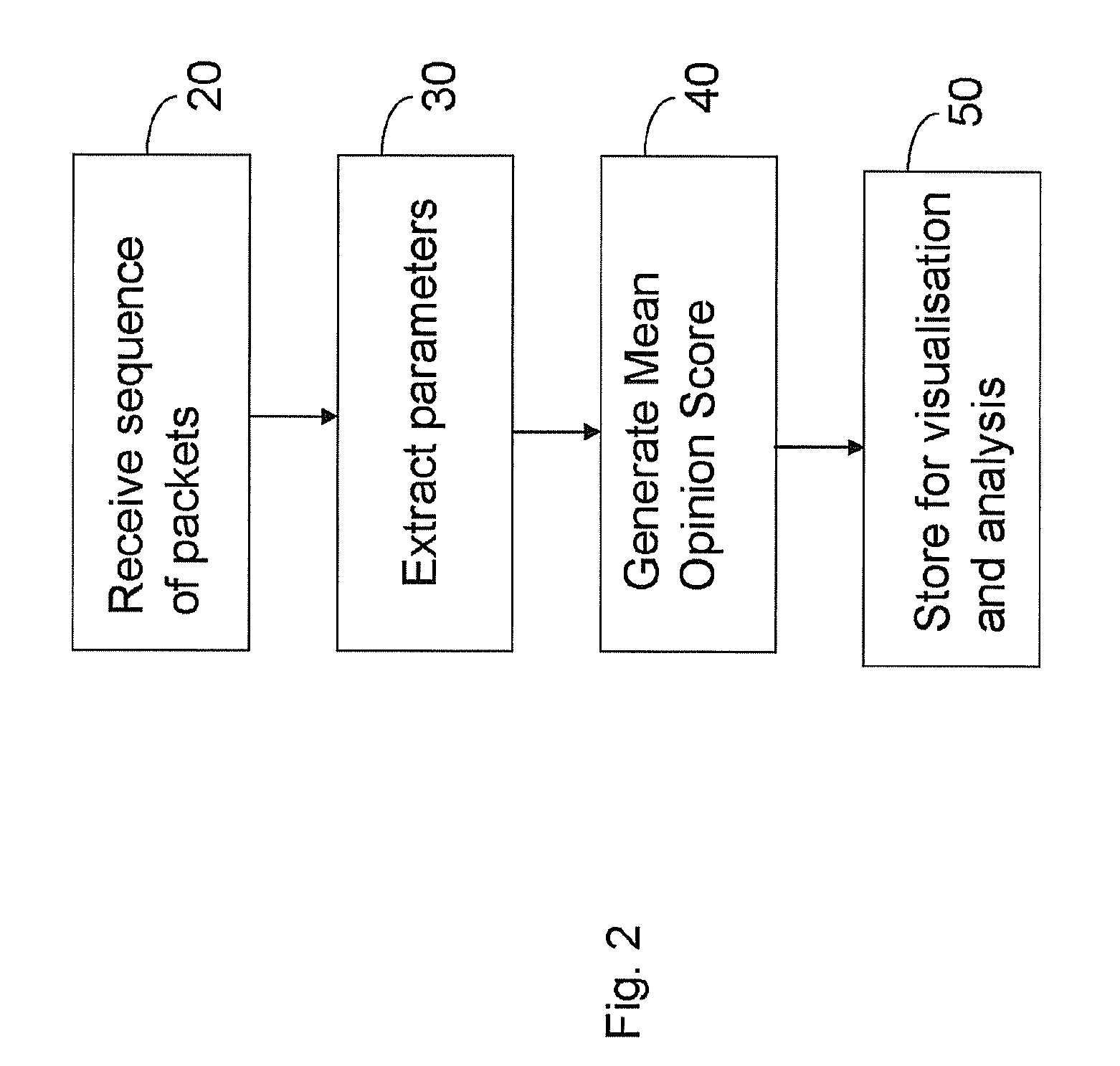

Image

  • Video quality assessment
  • Video quality assessment
  • Video quality assessment

Examples


Embodiment Construction

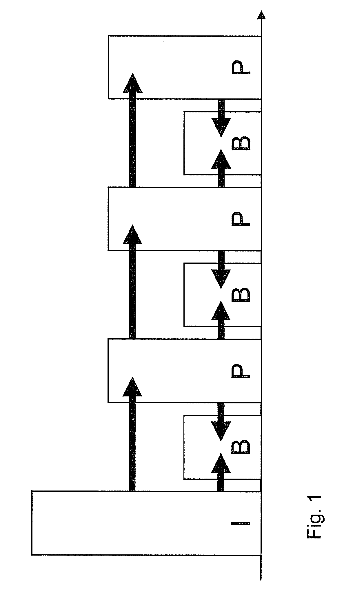
[0032]Referring now to FIG. 1, encoding using I-frames B-frames and P-frames is illustrated. The advantage of using P and B-frames is that they only encode the difference between the frame to be encoded and another frame, and can therefore be encoded using fewer bits than the equivalent I-frame. However, P and B-frames suffer from a problem called error-propagation whereby an error in one frame will also affect any frames that are based on it. Most recent video coding standards support I, P and B frames, including MPEG-2 part 2, MPEG-4 part 2, MPEG-4 Part 10 (H.264), H.263 and VC-1, with the more recent standards extending the concept of I, P and B encoding to slices of pictures in addition to whole frames.

[0033]The result of such video coding approaches is that successive encoded video frames can vary widely in their size in bytes and their sensitivity to errors. Moreover the bit-rates required to transport video images dictate that each video encoded frame must often be divided in...


PUM


Abstract

The present invention relates to the problem of estimating the effect of packet transmission impairments, including packet loss, on the subjective quality of a video transmission where frames of data relating to the same video frame or field are permitted to span more than one packet. The invention provides a method of assessing quality of a video signal comprising a sequence of video frames received via a packet switched network using a parameter which is a weighted sum of two counters where the first counter is incremented in dependence of the total number of packets in frames determined to have been received with one or more lost packets and the second counter is incremented in dependence of the number of packets following the first lost packet in each frame and the lost packet itself.

Description

BACKGROUND[0001]a. Field of the Invention[0002]The present invention relates to the problem of estimating the effect of packet transmission impairments, including packet loss, on the subjective quality of a video transmission where frames of data relating to the same video frame or field are permitted to span more than one packet.[0003]The invention has particular application in a class of multimedia quality prediction models that predict the effect of packet transmission impairments on the perceived quality of a media stream.[0004]In “VoIP Quality Assessment: Taking Account of the Edge-Device”, S R Broom, IEEE Trans on Audio, Speech and Language Processing, Vol 14, No. 6, November 2006, pp 1977-1983, Broom describes a model that predicts the effect of packet transmission impairments on the perceived, or subjective, quality of a voice over internet protocol (VoIP) call. The prediction is based on passive analysis of the packet stream carrying the voice data and can be performed at m...

Claims


Application Information

Patent Timeline
Patent Type & Authority Patents(United States)
IPC IPC(8): G01R31/08
CPCH04N17/004H04N19/172H04N19/61H04N19/154H04N19/89H04N19/188
Inventor ISAMBART, MARCBROOM, SIMON
Owner PSYTECHNICS
Learn More