Device and method of detecting signal delay

a signal delay and detection method technology, applied in the direction of electronic circuit testing, measurement devices, instruments, etc., can solve the problems of signal distortion, oscilloscopes are expensive, and signal delay in a circui

Inactive Publication Date: 2016-05-26
UNIVERSAL SCIENTIFIC INDUSTRIAL (SHANGHAI) CO LTD
View PDF5 Cites 2 Cited by
  • Summary
  • Abstract
  • Description
  • Claims
  • Application Information

AI Technical Summary

Problems solved by technology

The parasitic capacitance may give rise to a signal delay in a circuit.
However, an oscilloscope is expensive, and the wide variety of capabilities provided by an oscilloscope may be unnecessary to accomplish a measurement task.
Additionally, the sampling rates of many oscilloscopes are insufficient to sample high-frequency signals; therefore, sampling of a high-frequency signal may result in a distorted signal, and such distortion may lead to measurement inaccuracy.

Method used


Image

  • Device and method of detecting signal delay
  • Device and method of detecting signal delay
  • Device and method of detecting signal delay

Examples


Embodiment Construction

[0020]The present disclosure describes a technique for detecting a signal delay, which may be implemented with relatively low cost, and which may provide improved accuracy for measuring signal delays of high-frequency signals.

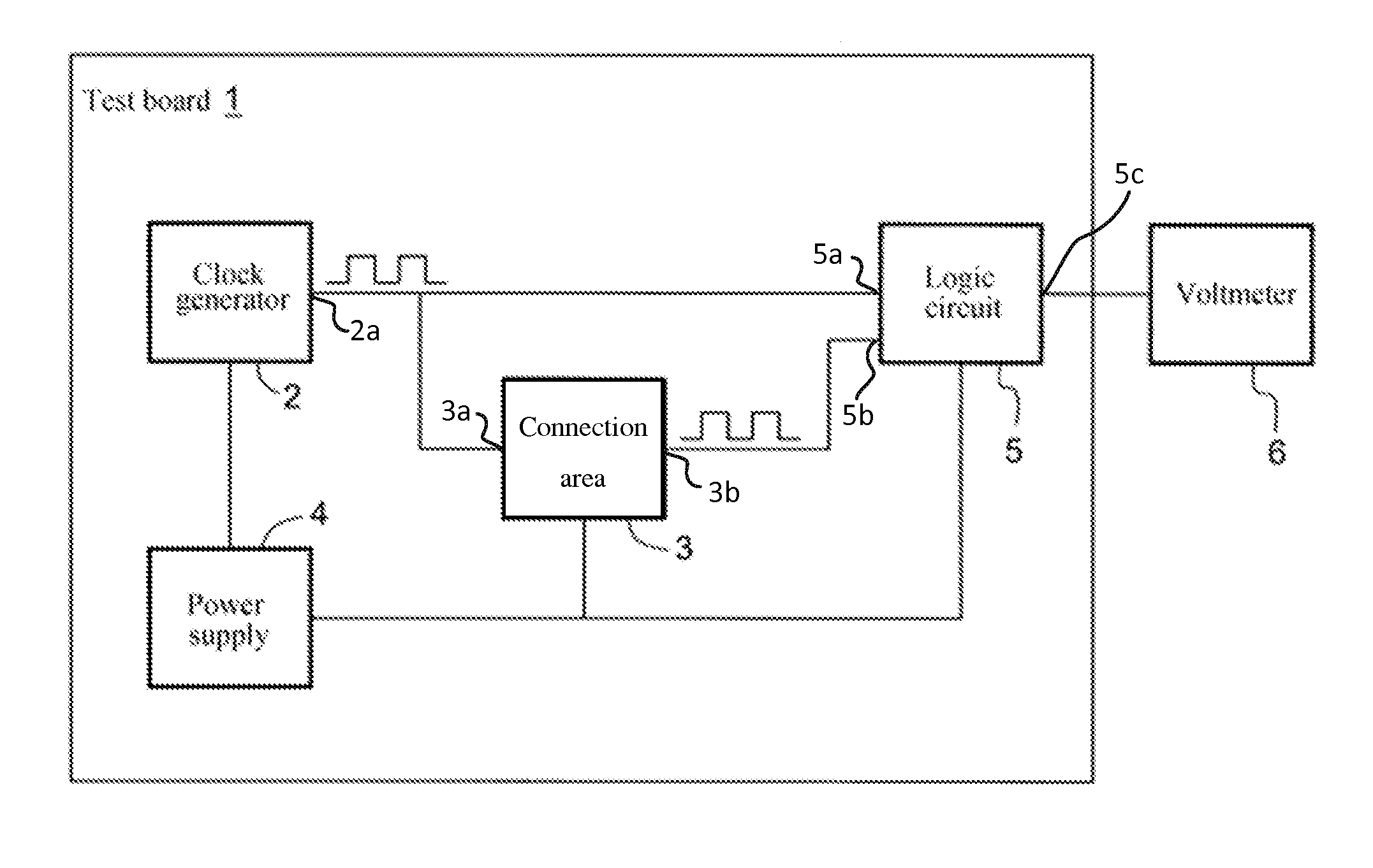
[0021]FIG. 1 is a block diagram of a system for detecting a signal delay according to an embodiment of the present disclosure. As shown in FIG. 1, a test board 1 includes a clock generator 2, a connection area 3, a power supply 4, and a logic circuit 5.

[0022]The test board 1 is a circuit board, which may be a printed circuit board or another suitable circuit board. The test board 1 may be a single-sided board, a double-sided board, or a multi-layer board.

[0023]The clock generator 2 is a circuit that is capable of generating signals at different frequencies. For example, the clock generator 2 may generate signals at a first frequency for a first test, at a second frequency for a second test, and at other frequencies for other tests. For another example, the cloc...


PUM


Abstract

The present disclosure discloses a device for, and a method of, detecting a signal delay. The method of detecting a signal delay includes inputting a first signal and a second signal to a logic circuit to obtain an output signal; measuring an average voltage of the output signal; and determining a delay time of the second signal relative to the first signal based on a difference between the average voltage of the output signal and a reference voltage. The device for detecting a signal delay includes a clock output of a clock generator connected to a first logic input of a logic circuit and to a connection area for receiving a circuit to be tested. A second logic input of the logic circuit is also connected to the connection area. The voltage measurement device is connected to a logic output of the logic circuit.

Description

CROSS-REFERENCE TO RELATED PATENT APPLICATIONS[0001]This application claims the benefit of and priority to Chinese Patent Application No. 201410696186.9, filed on Nov. 26, 2014, the content of which is incorporated herein by reference in its entirety.BACKGROUND[0002]1. Technical Field[0003]The present disclosure relates to a signal detecting device and method, and more particularly to a method and device of detecting a delay time of an output signal of a circuit.[0004]2. Description of the Related Art[0005]Integrated circuits (ICs) implement increasingly more functions and are of decreasingly smaller size, while expected to have increasingly improved performance. However, impact from parasitic capacitance in a semiconductor component becomes more notable as feature size is reduced. The parasitic capacitance may give rise to a signal delay in a circuit. A measurement of signal delay can be a useful parameter for estimating the performance of a circuit. Therefore, it may be desirable ...

Claims


Application Information

Patent Timeline
Patent Type & Authority Applications(United States)
IPC IPC(8): G01R31/28
CPCG01R31/2886G01R31/2882G01R31/31725
Inventor LI, KUAN-HSING
Owner UNIVERSAL SCIENTIFIC INDUSTRIAL (SHANGHAI) CO LTD
Why Eureka
Try Eureka