
Electronic apparatus

a technology of electronic equipment and components, applied in the field of electronic equipment, can solve the problems of achieve the effect of reducing the degree of freedom in the installment of those components and increasing the number of components and costs

Inactive Publication Date: 2010-12-21
SONY CORP
View PDF5 Cites 130 Cited by
  • Summary
  • Abstract
  • Description
  • Claims
  • Application Information

AI Technical Summary

Benefits of technology

[0009]However, the jog dial disclosed in Japanese Patent Application Laid-open No. 2005-228043 still can only be pressed from one direction even though rotating operations in a plurality of directions and allocation of a plurality of functions (moving the cursor in the vertical and horizontal directions) have become possible, thereby resulting in inconvenience. Further, it may be necessary to prepare an operation input unit such as a button in addition to the jog dial for the plurality of functions to be executed through pressing operations in that state, leading to an increase in the number of components and costs. Moreover, an installment space for components other than the operation input unit is accordingly reduced, whereby a degree of freedom in installment of those components decreases.

Problems solved by technology

However, the jog dial disclosed in Japanese Patent Application Laid-open No. 2005-228043 still can only be pressed from one direction even though rotating operations in a plurality of directions and allocation of a plurality of functions (moving the cursor in the vertical and horizontal directions) have become possible, thereby resulting in inconvenience.
Further, it may be necessary to prepare an operation input unit such as a button in addition to the jog dial for the plurality of functions to be executed through pressing operations in that state, leading to an increase in the number of components and costs.

Method used


Image

  • Electronic apparatus
  • Electronic apparatus
  • Electronic apparatus

Examples


first embodiment

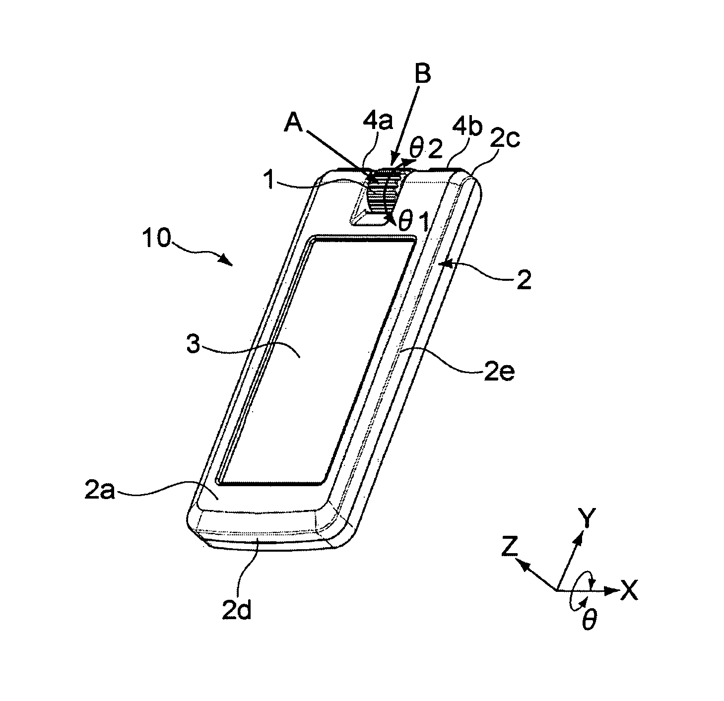
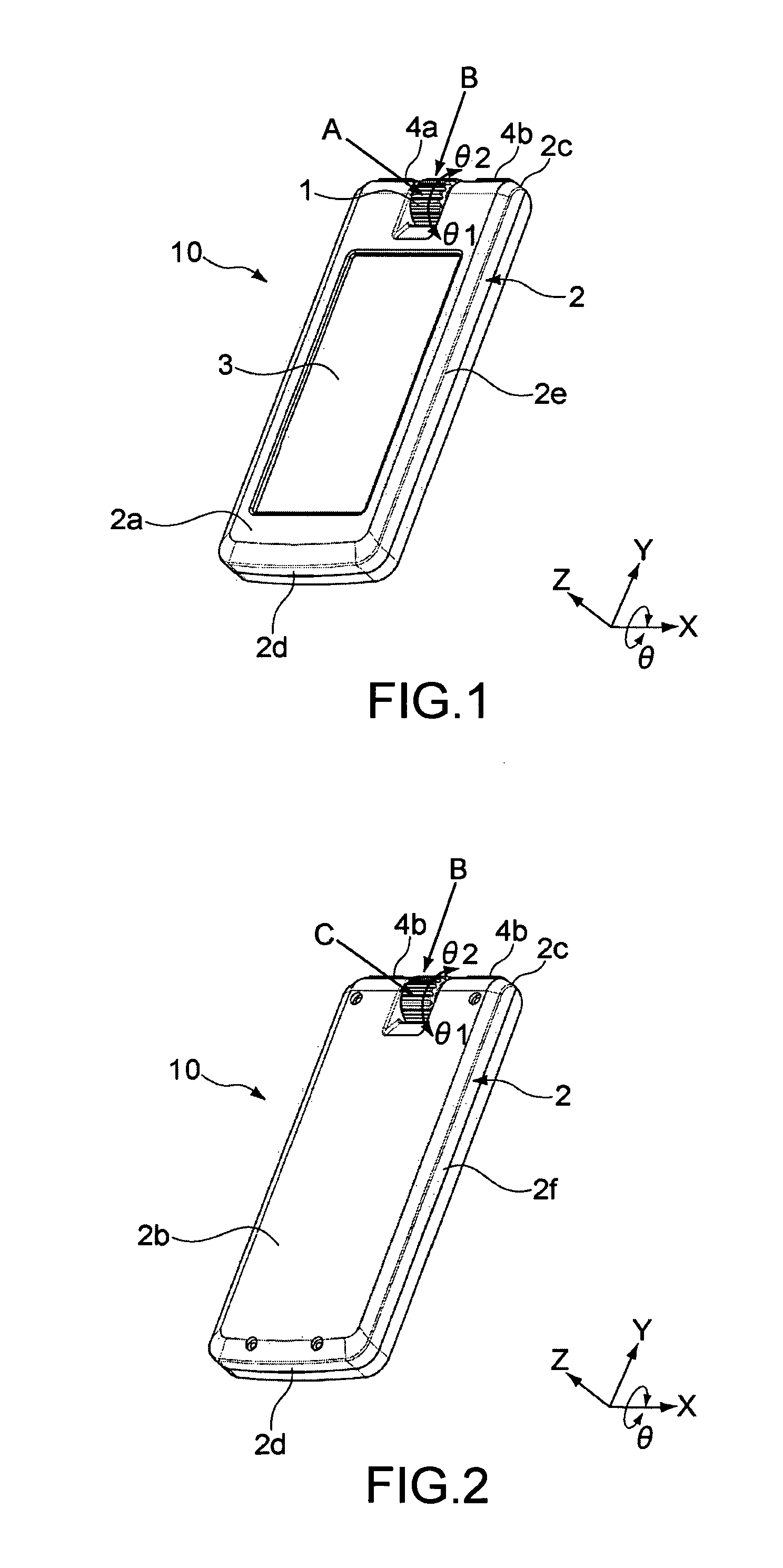
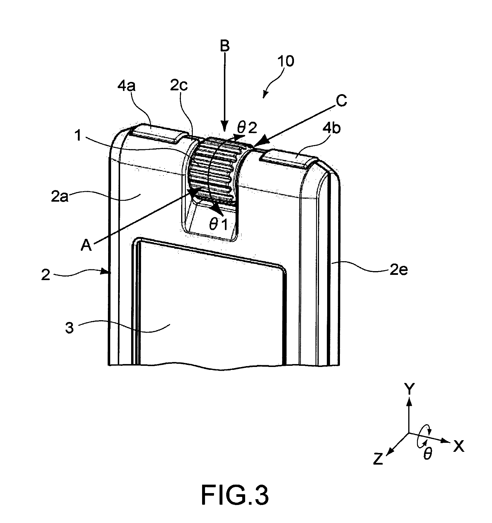
[0092]First, a description will be given of a first embodiment of the present invention. In this embodiment, as an electronic apparatus, a multimedia player capable of reproducing various contents including a music content and a moving image content is applied. FIG. 1 is a perspective view of a multimedia player 10 seen from a front surface direction according to this embodiment. FIG. 2 is a perspective view of the multimedia player 10 shown in FIG. 1 seen from a back surface direction. Further, FIG. 3 is an enlarged view of the multimedia player 10 in the vicinity of a jog dial 1.

[0093]As shown in those figures, a casing 2 of the multimedia player 10 includes a front surface 2a, a back surface 2b, an upper surface 2c, a lower surface 2d, a right-hand side surface 2e, and a left-hand side surface 2f. The front surface 2a of the casing 2 is provided with, for example, a display unit 3 including a liquid crystal panel composed of a TFT (Thin Film Transistor) and the like. The casing 2...

second embodiment

[0125]Next, a second embodiment of the present invention will be described. In this embodiment, parts having the same structures and functions as in the first embodiment are denoted by the same reference numerals and descriptions thereof will be omitted or simplified. In this embodiment, the present invention is applied to a portable music player as the electronic apparatus capable of reproducing music contents.

[0126]FIG. 10 is a perspective view of a music player 50 seen from a front surface direction according to this embodiment. Further, FIG. 11 is a perspective view of the music player 50 seen from the back surface direction. The music player 50 is of a size that can be grasped by hand.

[0127]As shown in those figures, a casing 52 of the music player 50 includes a front surface 52a, a back surface 52b, an upper surface 52c, a lower surface 52d, a right-hand side surface 52e, and a left-hand side surface 52f. A jog dial 51 is provided in the middle of the upper portion of the casi...

third embodiment

[0160]Next, a third embodiment of the present invention will be described. In this embodiment, parts having the same structures and functions as in the second embodiment are denoted by the same reference numerals and descriptions thereof will be omitted or simplified. In the music player of this embodiment, a mechanism for holding the rotating operation of the user in the θ1 and θ2 directions is particularly different from that of the second embodiment.

[0161]FIG. 19 are diagrams showing states in the vicinity of a hold switch 54 before and after the hold operation of the music player. It should be noted that in the figures, for brevity of description, illustration of the tact switches 61 and the second inner circumferential surface 64 is omitted. FIG. 19A is a front view of the music player 70 showing the internal structure of the jog dial 51 when the hold switch 54 is in the off state, FIG. 19B is a back view of the music player 70 when the hold switch 54 is in the off state, FIG. ...


PUM


Abstract

Provided is an electronic apparatus including a casing, a first jog dial, and a pressing operation detection unit. The casing includes a first surface and a second surface. The first jog dial is exposed from the first surface and the second surface, is capable of rotating around a first axis substantially parallel to the first surface and the second surface as a center, and is capable of being pressed from a first direction substantially perpendicular to the first surface and a second direction substantially perpendicular to the second surface. The pressing operation detection unit detects a first pressing operation from the first direction and a second pressing operation from the second direction.

Description

CROSS REFERENCES TO RELATED APPLICATIONS[0001]The present invention contains subject matter related to Japanese Patent Application JP 2007-048482 filed in the Japanese Patent Office on Feb. 28, 2007, the entire contents of which being incorporated herein by reference.BACKGROUND OF THE INVENTION[0002]1. Field of the Invention[0003]The present invention relates to an electronic apparatus including a jog dial.[0004]2. Description of the Related Art[0005]Up to now, jog dials have been used as operation input devices in electronic apparatuses such as a PC (Personal Computer), cellular phone, PDA (Personal Digital Assistants), and portable AV (Audio Video) apparatus.[0006]The jog dials have a nearly cylindrical shape or a disc shape, and functions are respectively allocated to positive and negative rotating operations with a rotation axis as a center (for example, moving a cursor in a vertical or horizontal direction). Further, one function (for example, determination of a selection item)...

Claims


Application Information

Patent Timeline
Patent Type & Authority Patents(United States)
IPC IPC(8): H04M1/00G06F3/0338G06F3/0362
CPCG06F1/1616G06F1/1626G06F1/169G06F3/0362G06F3/0482H04M1/233H04M1/72558H04M1/72442
Inventor TSUCHIYA, RYOMIYASHITA, HISAYA
Owner SONY CORP
Learn More