
LED lamp assembly having heat pipes and finned heat sinks

a technology of heat pipes and heat sinks, which is applied in the direction of fixed installation, lighting and heating equipment, lighting support devices, etc., can solve the problems of increased heat output, increased power consumption, and increased module cos

Inactive Publication Date: 2010-12-28
FU ZHUN PRECISION IND SHENZHEN +1
View PDF10 Cites 60 Cited by
  • Summary
  • Abstract
  • Description
  • Claims
  • Application Information

AI Technical Summary

Benefits of technology

The LED lamp assembly described in this patent has a unique design that allows for a wide range of illumination. It includes a first heat sink with a through hole and first fins, multiple second heat sinks with second fins facing the first fins, and heat pipes that connect the first and second heat sinks. The LED modules are attached to the second heat sinks and face outward, allowing for coverage of a large area. The heat generated by the LED modules is dissipated by the second heat sinks and the first heat sink via the heat pipes. The technical effect of this design is a more efficient and effective LED lamp assembly for illumination purposes.

Problems solved by technology

The large number of LEDs leads to a more expensive module and one with greater power consumption.
The greater power usage leads to greater heat output, which, if not adequately addressed at additional expense, impacts the LED lamp assembly reliability.
Besides, since the LEDs are generally arranged on a printed circuit board which has a flattened surface, the LEDs acting as a light source and arranged in this way usually are failed to provide a three-dimensional lamplight for a condition that needs even and large-scale light.

Method used


Image

  • LED lamp assembly having heat pipes and finned heat sinks
  • LED lamp assembly having heat pipes and finned heat sinks
  • LED lamp assembly having heat pipes and finned heat sinks

Examples


Embodiment Construction

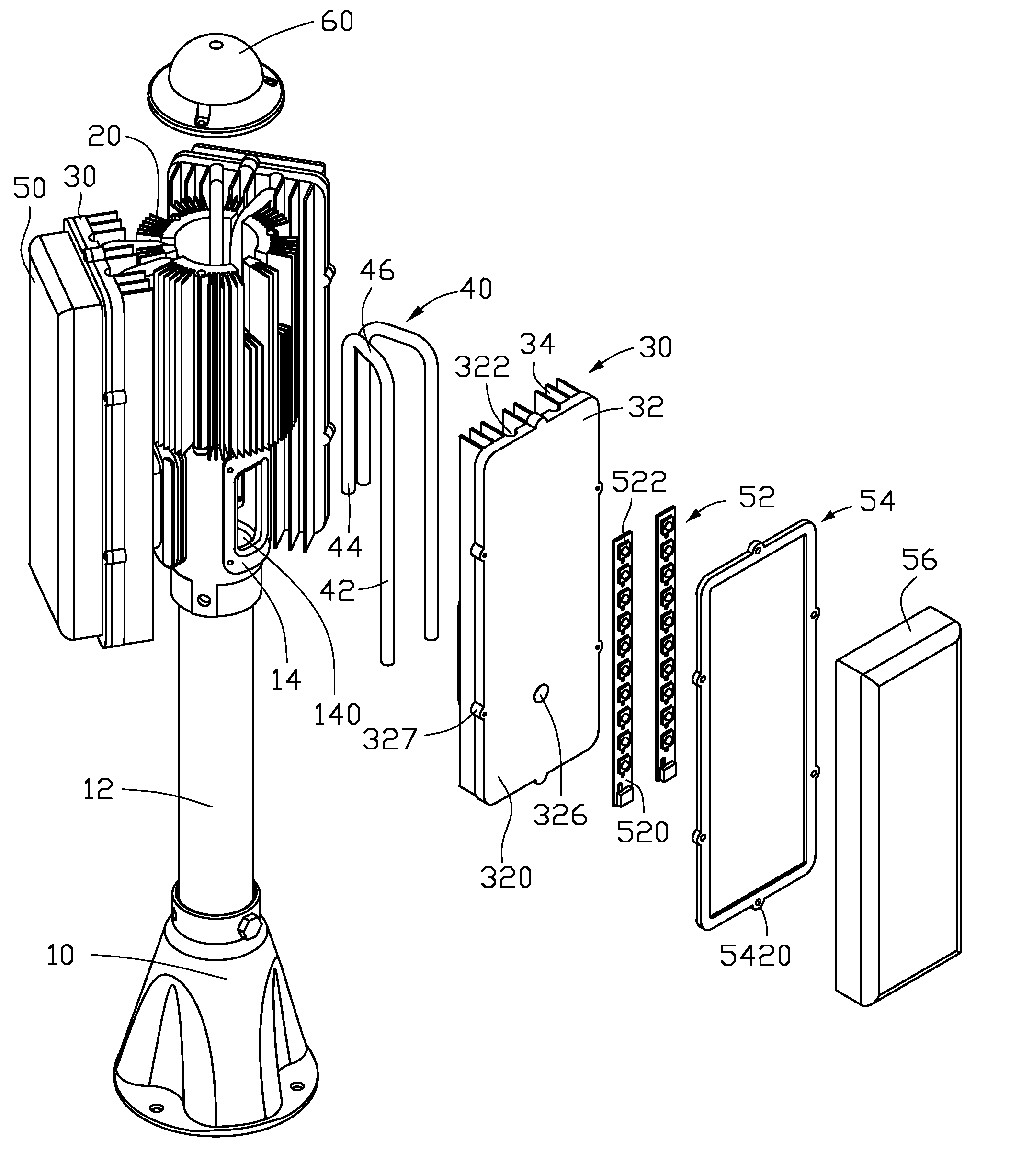
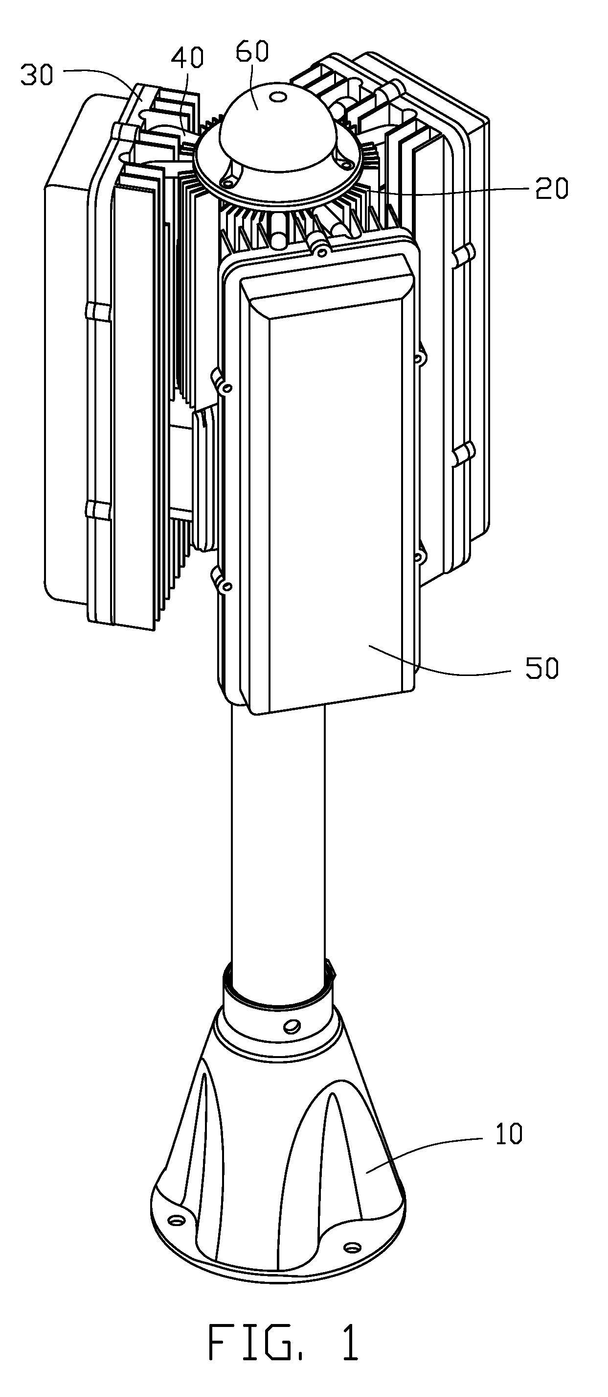
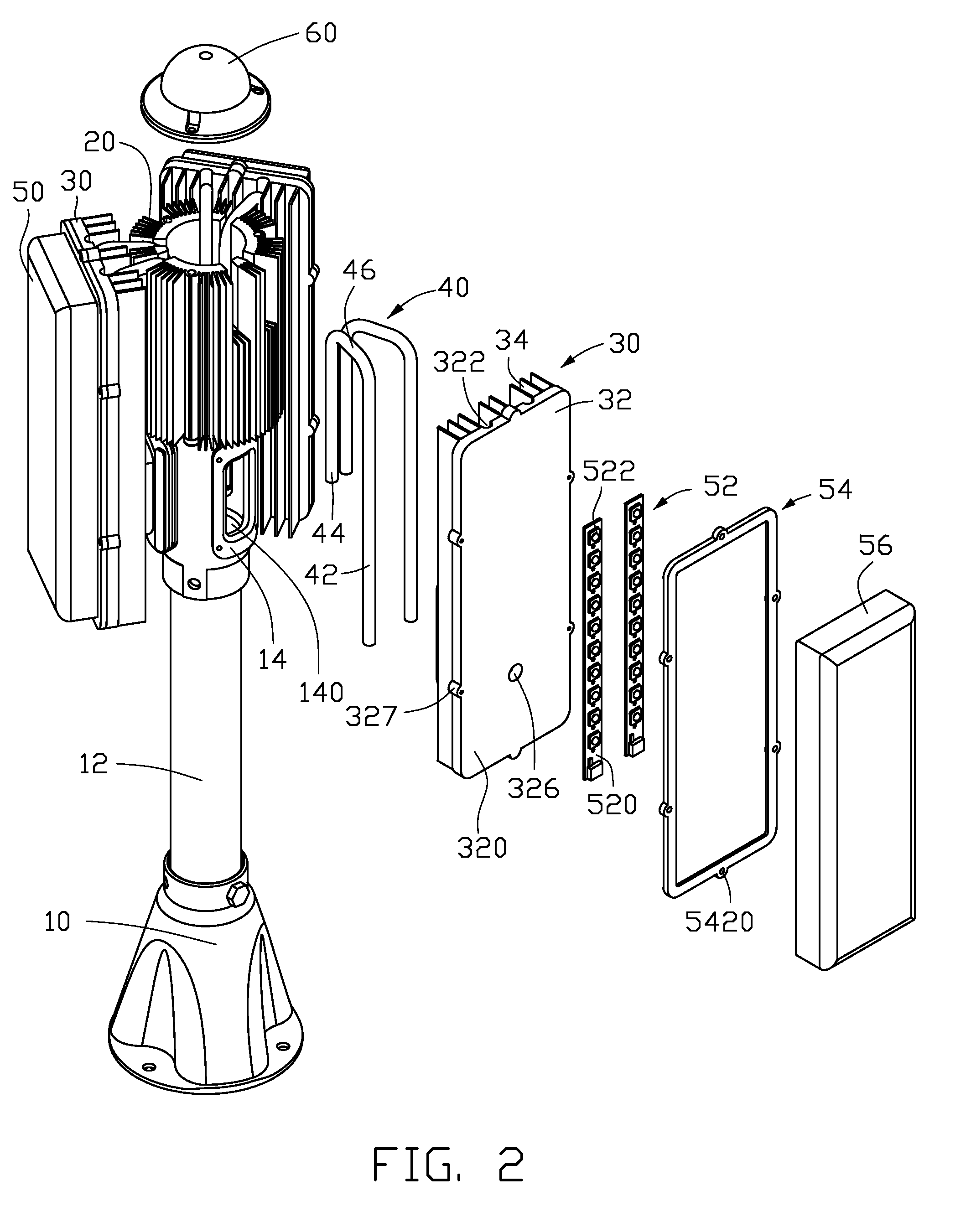
[0016]Referring to FIGS. 1-2, an LED lamp assembly for a lighting purpose in accordance with a preferred embodiment of the present invention is shown. The LED lamp assembly comprises a first heat sink 20, three second heat sinks 30 located around a periphery of the first heat sink 20, three LED modules 50 respectively thermally attached to outer sidewalls of the second heat sinks 30 and three groups of heat pipes 40 connecting the second heat sinks 30 with the first heat sink 20.

[0017]The LED lamp assembly further comprises a top cover 60 covering a top of the first heat sink 20. The LED lamp assembly can be held at a predetermined position by a supporting post 10 engaging with the first heat sink 20. In this embodiment, the supporting post 10 extends upwardly to support the first heat sink 20 on a top thereof. The supporting post 10 comprises a cylindrical lamp holder 12, which supports the first heat sink 20 on a top thereof. The lamp holder 12 has three engaging portions 14 exten...


PUM


Abstract

An LED lamp assembly includes a first heat sink, a plurality of second heat sinks secured to a periphery of the first heat sink, a plurality of LED modules respectively attached to the second heat sinks and a plurality of heat pipes interconnecting the first heat sink and the second heat sinks. The first heat sink comprises a heat conducting body defining a through hole therein and a plurality of first fins around the heat conducting body. The second heat sinks each comprise a plurality of second fins facing the first fins of the first heat sink. The heat pipes each comprise an evaporating section attached to a corresponding second heat sink and a condensing section extending into the through hole of the heat conducting body of the first heat sink and attached to the heat conducting body.

Description

BACKGROUND OF THE INVENTION[0001]1. Field of the Invention[0002]The present invention relates to an LED lamp assembly for a lighting purpose, and more particularly relates to an improved LED lamp assembly having a good heat dissipation capability and large illumination area.[0003]2. Description of Related Art[0004]An LED lamp assembly is a type of solid-state lighting that utilizes light-emitting diodes (LEDs) as a source of illumination. An LED is a device for transferring electricity to light by using a theory that, if a current is made to flow in a forward direction through a junction region comprising two different semiconductors, electrons and holes are coupled at the junction region to generate a light beam. The LED has an advantage that it is resistant to shock, and has an almost eternal lifetime under a specific condition; thus, the LED lamp assembly is intended to be a cost-effective yet high quality replacement for incandescent and fluorescent lamps.[0005]Known implementat...

Claims


Application Information

Patent Timeline
Patent Type & Authority Patents(United States)
IPC IPC(8): F21V29/00
CPCF21K9/00F21V29/006F21V29/763F21V29/717F21V29/75F21S8/032F21V29/89F21V29/773F21V29/51
Inventor LONG, BINYU, GUANG
Owner FU ZHUN PRECISION IND SHENZHEN
Learn More