Optical pickup and optical disc apparatus

a technology of optical disc and optical pickup, which is applied in the direction of optical recording heads, instruments, data recording, etc., can solve the problems of increasing noise levels, decreasing the output power of laser diodes, etc., and achieve good reproducing characteristics and reduce the intensity of optical beams emitted to optical discs.

Inactive Publication Date: 2010-12-28
SONY CORP
View PDF5 Cites 0 Cited by
  • Summary
  • Abstract
  • Description
  • Claims
  • Application Information

AI Technical Summary

Benefits of technology

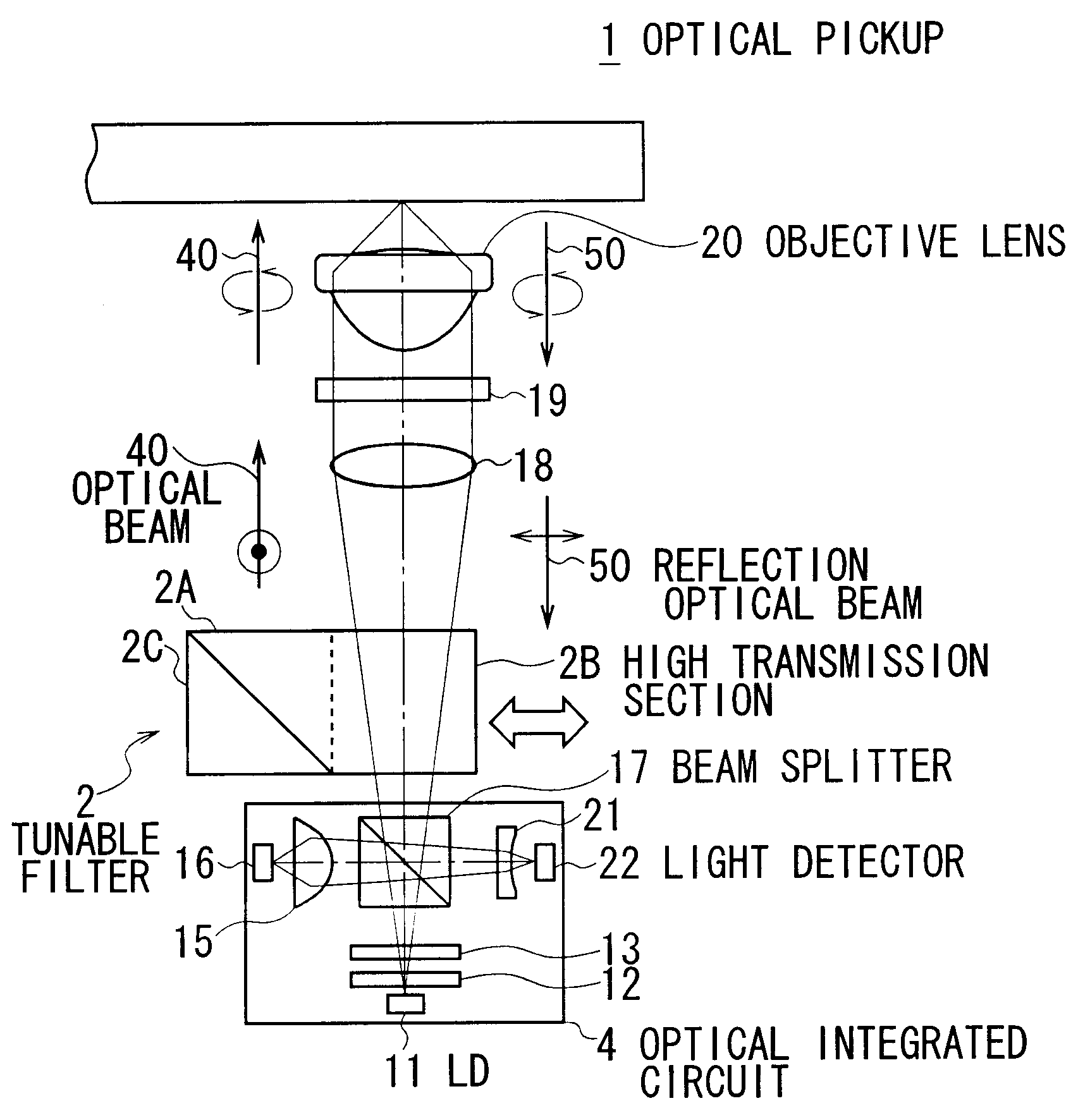
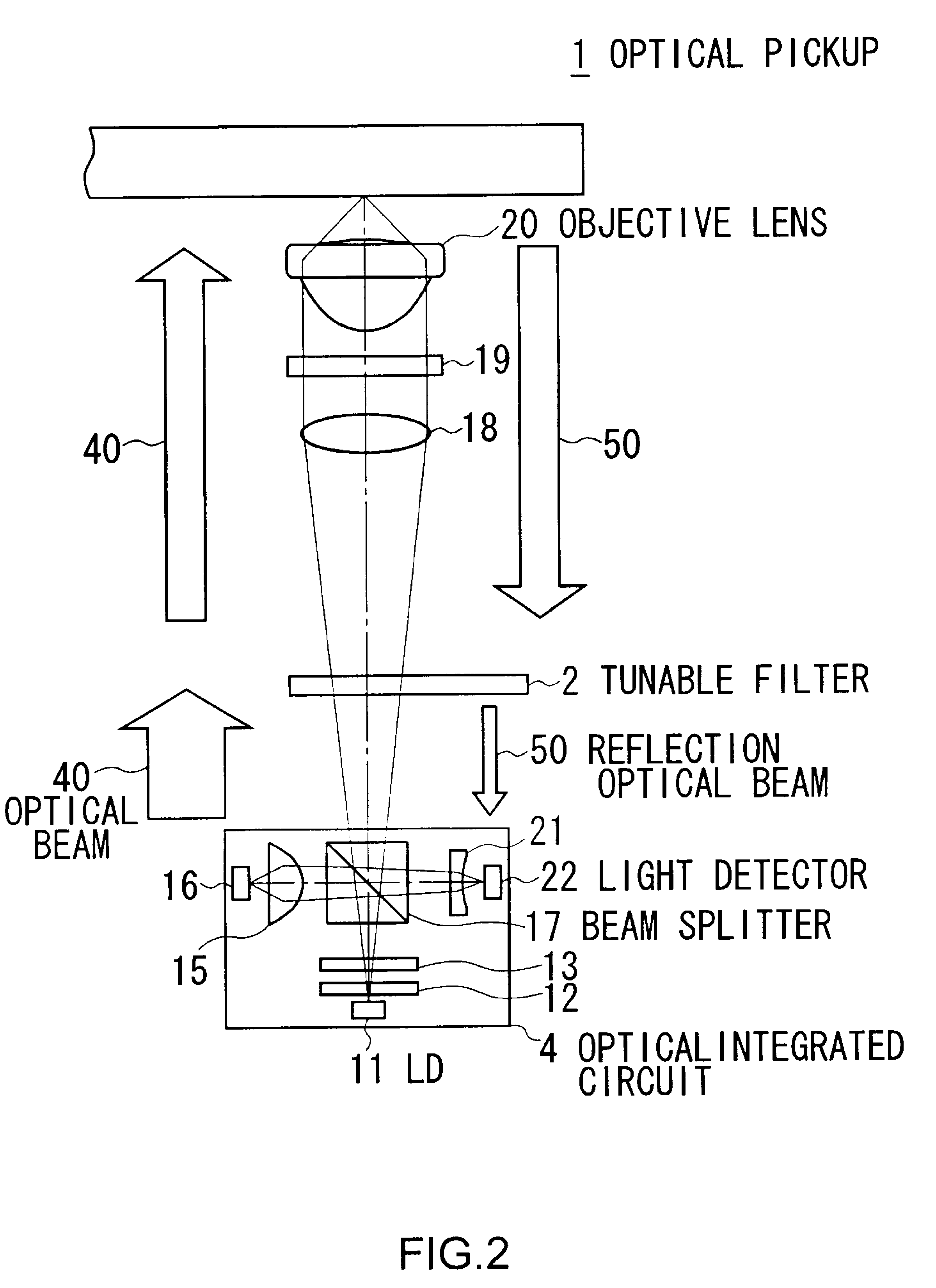
[0012]The present invention has been made in view of the above points and is intended to provide an optical pickup and an optical disc apparatus with good reproducing characteristics even when its neutral density filter section is placed on the mutual optical path of the optical beam and the reflection optical beam.
[0014]Accordingly, only the intensity of the optical beam emitted to the optical disc can be reduced when placing the neutral density filter section in the optical path. This allows the neutral density filter section to be placed in the mutual optical path of the optical beam and the reflection optical beam.
[0015]In this manner, only the intensity of the optical beam emitted to the optical disc can be reduced when placing the neutral density filter section in the optical path. Thus, the optical pickup and the optical disc apparatus according to an embodiment of the present invention present good reproducing characteristic even when the neutral density filter section is placed in the mutual optical path of the optical beam and the reflection optical beam.

Problems solved by technology

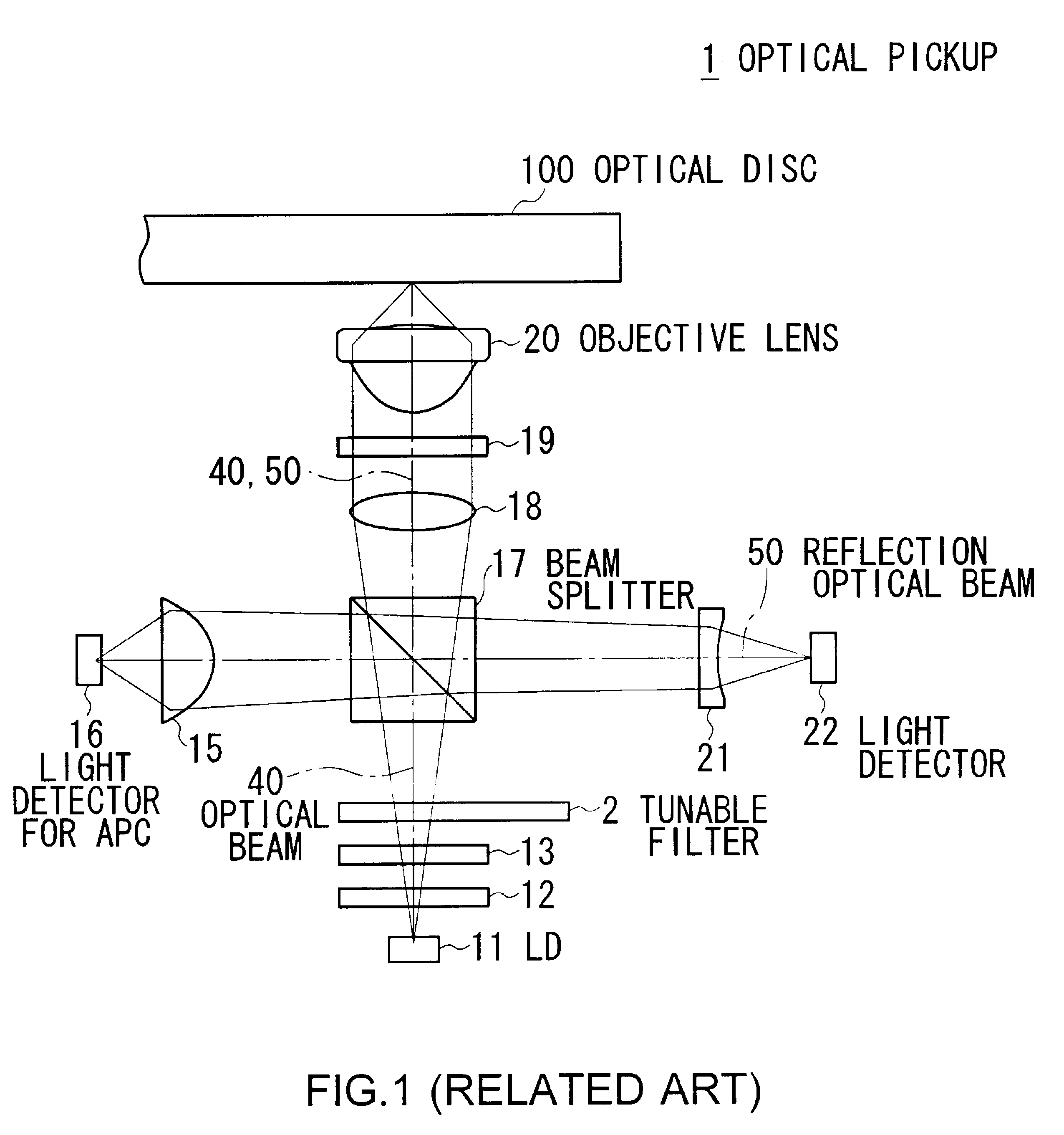
However, decreasing the output power of the laser diode increases noise levels compared to the intensity of the optical beam emitted.

Method used


Image

  • Optical pickup and optical disc apparatus
  • Optical pickup and optical disc apparatus
  • Optical pickup and optical disc apparatus

Examples


Embodiment Construction

[0026]An embodiment of the present invention will be described in detail with reference to the accompanying drawings.

(1) Overall Configuration of an Optical Disc Apparatus

[0027]In FIG. 3, the reference numeral 3 denotes an optical disc apparatus as a whole. The parts of FIG. 3 are represented as the same reference numerals and symbols as the corresponding parts of FIGS. 1 and 2. The optical disc apparatus 3 supports two types of the optical disc 100: an one layer disc 100a, such as Compact Disc (CD), including one signal recording layer; and a two layer optical disc 100b, such as “Blu-ray Disc (BD) (Registered Trademark)”, including two signal recording layers.

[0028]A control section 32 controls components of the optical disc apparatus 3. The control section 32 includes Central Processing Unit (CPU), Read Only Memory (ROM) in which various programs are stored, and Random Access Memory (RAM) which serves as a work memory for the CPU.

[0029]The control section 32 controls a servo circu...


PUM

PropertyMeasurementUnit
transmittanceaaaaaaaaaa

Abstract

An optical pickup includes: a light source; an objective lens; a beam splitter; a quarter wave plate that transforms the optical beam into a circularly polarized optical beam and also transforms the circularly polarized reflection optical beam into an optical beam whose polarization direction is perpendicular to the optical beam; a light detector; a neutral density filter section placed on a mutual optical path of those beams, reducing the intensity of the optical beam while maintaining the intensity of the reflection optical beam; and a filter drive section that puts the neutral density filter section in the mutual optical path or outside of it, wherein the intensity of the optical beam and the filter drive section are controlled such that the amount of the optical beam emitted to the optical disc is maintained at a predetermined level.

Description

CROSS REFERENCES TO RELATED APPLICATIONS[0001]The present invention contains subject matter related to Japanese Patent Application JP 2006-189364 filed in the Japanese Patent Office on Jul. 10, 2006, the entire contents of which being incorporated herein by reference.BACKGROUND OF THE INVENTION[0002]1. Field of the Invention[0003]The present invention relates to an optical pickup and an optical disc apparatus, and is preferably applied to an optical disc apparatus including an optical pickup in which a laser diode and a light detector are closely disposed or in which a laser diode and a beam splitter are closely disposed, for example.[0004]2. Description of Related Art[0005]An optical pickup is usually equipped with a laser diode. The laser diode is selected such that its rating is appropriate for recording: recording of information may require more intense emission light than reproduction of information.[0006]The optical pickup may need to dramatically decrease the output power of ...

Claims


Application Information

Patent Timeline
Patent Type & Authority Patents(United States)
IPC IPC(8): G11B7/12
CPCG11B7/1381G11B2007/0006
Inventor SEO, KATSUHIRO
Owner SONY CORP
Why Eureka
Try Eureka