Optical recording medium and optical recording/reproducing method

a recording medium and optical recording technology, applied in the field of optical recording medium and optical recording/reproducing method, can solve the problems of difficult to realize high-density and large-capacity recording/reproducing, and achieve good reproducing characteristics, low cost, and low environmental damage

Inactive Publication Date: 2008-09-02
SONY CORP
View PDF11 Cites 0 Cited by
  • Summary
  • Abstract
  • Description
  • Claims
  • Application Information

AI Technical Summary

Benefits of technology

[0039]Furthermore, according to an optical recording medium on which recoding pits are formed by providing aforementioned concaves and convexes, it became possible to obtain a good reproducing characteristic as explained in detail relating to the embodiment mentioned hereinafter by constituting at least the recording portion of the optical recording medium with Si, Sic or a high refractive index glass, and in this case it can realize to obtain an optical recording medium for reproduction-only whose cost is a low and which has little environment harmfulness.
[0040]Further, the diameter of the light beam realized by the objective lens can be smaller by using an optical recording medium according to the invention and by selecting the thickness of an air layer between the objective lens and the optical recording medium equal to or less than 50 nm, so that it became possible to realize a near-field optical recording / reproducing with a certainly good recording / reproducing characteristic in an optical pickup apparatus and an optical recording / reproducing apparatus which can deal with an optical source having a wavelength from 200 nm to 500 nm and which is expected to be developed in response to a tendency of an optical recording medium of a higher density and a larger capacity.

Problems solved by technology

However, a good reproducing characteristic cannot be obtained even if the refractive index of the first optical lens is increased and the numerical aperture NA of the objective lens is increased, and as a result it becomes difficult to realize a high-density and a large-capacity recording / reproducing.

Method used


Image

  • Optical recording medium and optical recording/reproducing method
  • Optical recording medium and optical recording/reproducing method
  • Optical recording medium and optical recording/reproducing method

Examples


example 1

PRACTICAL EXAMPLE 1

[0100]This practical example shows a case where a lens constituted as an SIL type constitution is used for an objective lens as explained in the aforementioned FIG. 8.

[0101]As an objective lens an optical lens which is made by a high refractive index glass S-LAH79 material manufactured by OHARA INC. and was formed by cutting or working into 10 mm×10 mm in size and 2 mm in thickness and then optically grinded at both sides of the surfaces is used as the first optical lens.

[0102]The refractive index of this lens material was measured for the wavelengths from 380 nm to 800 nm using a spectroscopic ellipsometer VASE made by J.A. Woollam Japan Co., Inc. This result is shown in FIG. 12.

[0103]It can be seen from FIG. 12 that the high refractive index glass S-LAH79 has a relatively high refractive index as compared with other glass materials in the range of all wavelengths from 380 to 800 nm and the value thereof reaches 2.0 or more in the vicinity of a wavelength of 400 ...

example 2

PRACTICAL EXAMPLE 2

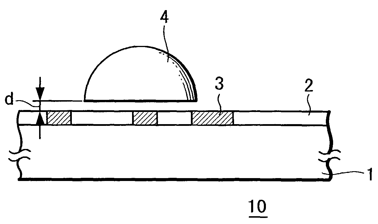
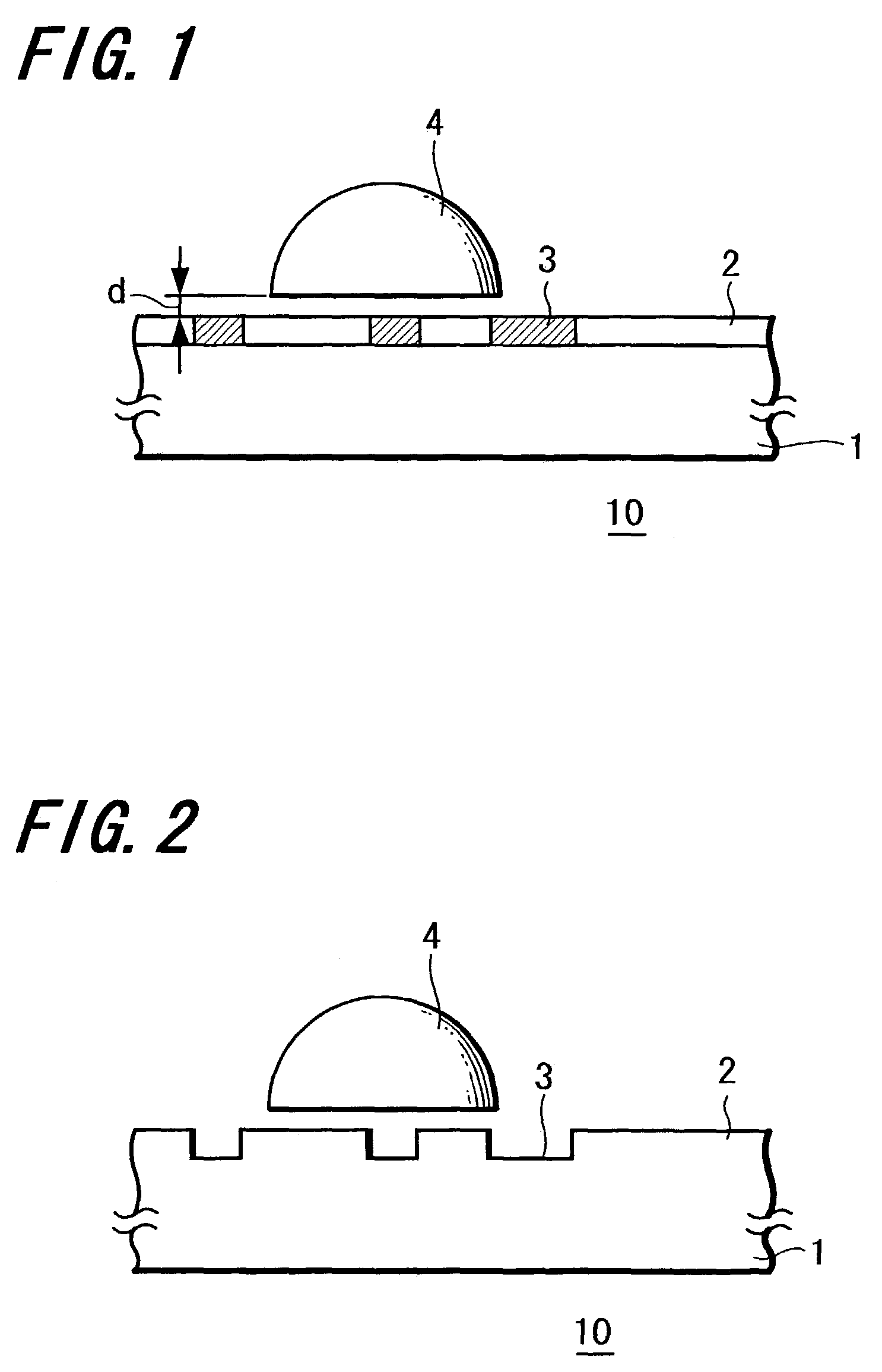
[0130]Next, a case where for the optical recording medium according to the present invention, concaves and convexes are provided on the recoding portion 2 corresponding to the recoding information and a so-called reproduction-only type is constituted by using these concaves and convexes as recording pits will be explained.

[0131]In this practical example 2, a case where a sample prepared by working a high refractive index glass S-LAH79 material made by OHARA INC. into a piece of 10 mm×10 mm in size and 2 mm in thickness and by optically grinding both the surfaces thereof is used as an optical lens as same as the objective lens used in the practical example 1 will be explained.

[0132]Then, a refractive index of the sample at wavelengths from 380 nm to 800 nm was measured by a spectroscopic ellipsometer VASE made by J.A. Woollam Japan Co., Inc. The dependency of a refractive index of this material upon the wavelength is as shown in the aforementioned FIG. 12.

[0133]As ...


PUM

PropertyMeasurementUnit
thicknessaaaaaaaaaa
refractive indexaaaaaaaaaa
oscillation wavelengthsaaaaaaaaaa

Abstract

An optical recording medium 10 on which recording/reproducing or reproducing is performed by irradiating a light by means of an objective lens 4 having a numerical aperture equal to or more than 1 wherein an optical recording portion 2 is provided at least at the outer most surface at the irradiation side of the optical recording medium 10 and a relation n≧NA is selected when the refractive index of the recording portion 2 is n and the numerical aperture of the objective lens 4 is NA. Accordingly, it can propose an optical recording medium and an optical recording/reproducing method suitable for a near-field optical recording method which uses an objective lens having a numerical aperture equal to or more than 1.

Description

[0001]This application claims priority to Japanese Patent Application Numbers JP2002-190873 filed Jun. 28, 2002 and JP2003-114859 Apr. 18, 2003 which are incorporated herein by reference.BACKGROUND OF THE INVENTION[0002]1. Field of the Invention[0003]The present invention relates to an optical recording medium with which recording / reproducing or reproducing is performed by irradiating a light thereto by means of at least an objective lens having a numerical aperture equal to or more than 1 and relates to its optical recording / reproducing method.[0004]2. Description of the Related Art[0005]The optical recording medium (or a magneto-optical recording medium) represented by a CD (Compact Disc), an MD (Mini Disc) and a DVD (Digital Versatile Disc) is widely utilized as a storage medium of music information, video information, data, programs and so on.[0006]However, based on the demands for a higher sound quality, a higher picture quality and a longer operable time in connection with mus...

Claims


Application Information

Patent Timeline
Patent Type & Authority Patents(United States)
IPC IPC(8): G11B11/00G11B7/24G11B7/004G11B7/135G11B7/1372G11B7/1374G11B7/1387G11B7/243G11B7/253
CPCG11B7/1374G11B7/1387G11B2007/13727
Inventor SHINODA, MASATAKASAITO, KIMIHIRO
Owner SONY CORP
Why Eureka
Try Eureka