
Method for installing a stanchion on a tile roof and system therefor

a technology of stanchion and tile roof, which is applied in the field of roofs, can solve the problems of troublesome installation of stanchion on the support of roof fixtures such as solar panel structures

Active Publication Date: 2011-01-04
WENCON DEV INC
View PDF41 Cites 103 Cited by
  • Summary
  • Abstract
  • Description
  • Claims
  • Application Information

AI Technical Summary

Problems solved by technology

With such tile roofs it is troublesome to install stanchions to support roof fixtures such as solar panel structures.

Method used


Image

  • Method for installing a stanchion on a tile roof and system therefor
  • Method for installing a stanchion on a tile roof and system therefor
  • Method for installing a stanchion on a tile roof and system therefor

Examples


second embodiment

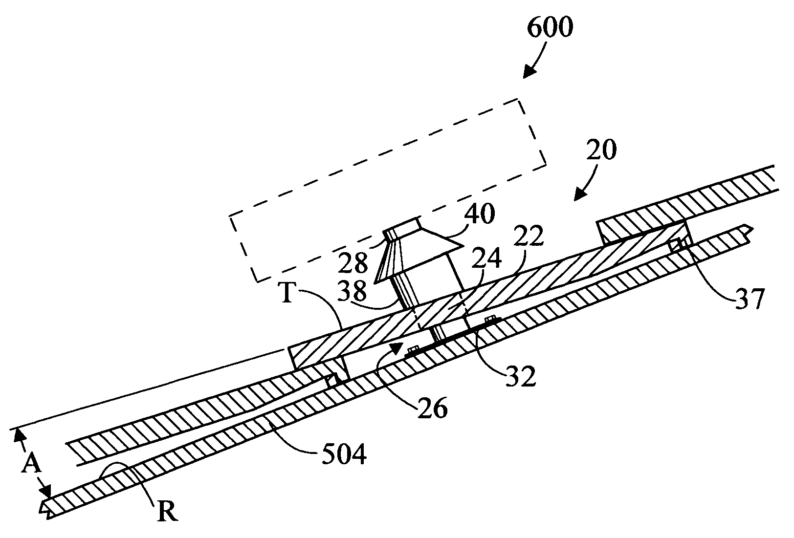
[0047]FIG. 17 is an enlarged side elevation view of tile 22. In this embodiment central axis 42 of sleeve 38 does not form an acute angle B with tile plane T as in FIG. 4, but is rather substantially perpendicular to tile plane T. The top surface 44 of sleeve 38 is inclined so that it forms an angle A with tile plane T. This facilitates the installation of seal 40.

[0048]FIGS. 18-20 are enlarged top perspective, enlarged top plan, and enlarged side elevation views respectively of a second embodiment tile, generally designated 122. Tile 122 has a double curve as opposed to the flat tile of tile 22. As with tile 22, tile 122 includes an aperture 124, a sleeve 138 which surrounds aperture 124 and which has a top surface 144 and a central axis 142. Tile 122 also includes a central longitudinal axis 150. When tile 122 is installed on roof 500, central axis 142 of tile 122 forms an angle A with roof plane 504. When tile 122 is viewed from the side (FIG. 20), central axis 142 of sleeve 138 ...

third embodiment

[0049]FIG. 21 is an enlarged top perspective view of a third embodiment tile, generally designated as 222. Tile 222 is a variation of tile 122 which has only one curve. Tile 222 includes sleeve 238 having a top surface 244, an aperture 224, and a central longitudinal axis 250. The angular relationships discussed above for tile 122 also apply to tile 222. Tile 222 cooperates with stanchion 26 and seal 40 in the same manner as is described above for tile 22.

[0050]In terms of use, a method for installing a stanchion 26 on a roof 500 includes:

[0051](a) providing a roof 500 having a plurality of existing tiles 502 disposed on top of roof sheathing 504;

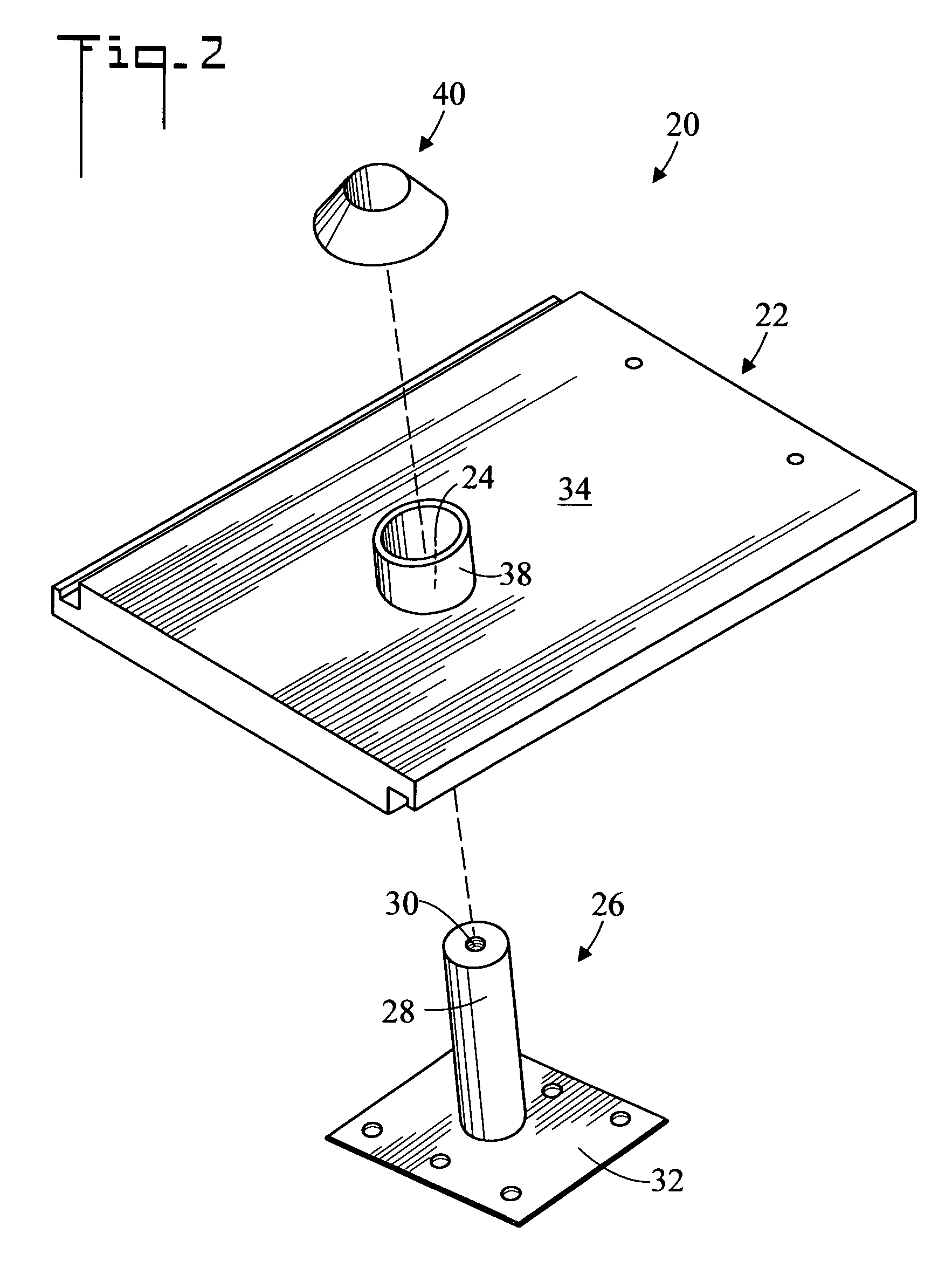
[0052](b) providing a system 20 for installing a stanchion 26 on roof 500 including:[0053]a tile 22 having an aperture 24;[0054]a stanchion 26 shaped and dimensioned to be received by aperture 24;

[0055](c) removing one of the existing tiles 502:

[0056](d) defining a position where stanchion 26 is to be connected to roof sheathing 504;

[0057](...


PUM


Abstract

A method and apparatus for installing a stanchion on a tile roof includes a tile which has an aperture and a stanchion which fits through the aperture. An existing roof tile is removed and the stanchion is connected to the roof sheathing at the place of removal. The tile is then placed over the stanchion so that the stanchion project through the aperture. In an embodiment of the invention, a sleeve surrounds the aperture and a seal provides a weather proof seal between the stanchion and the sleeve.

Description

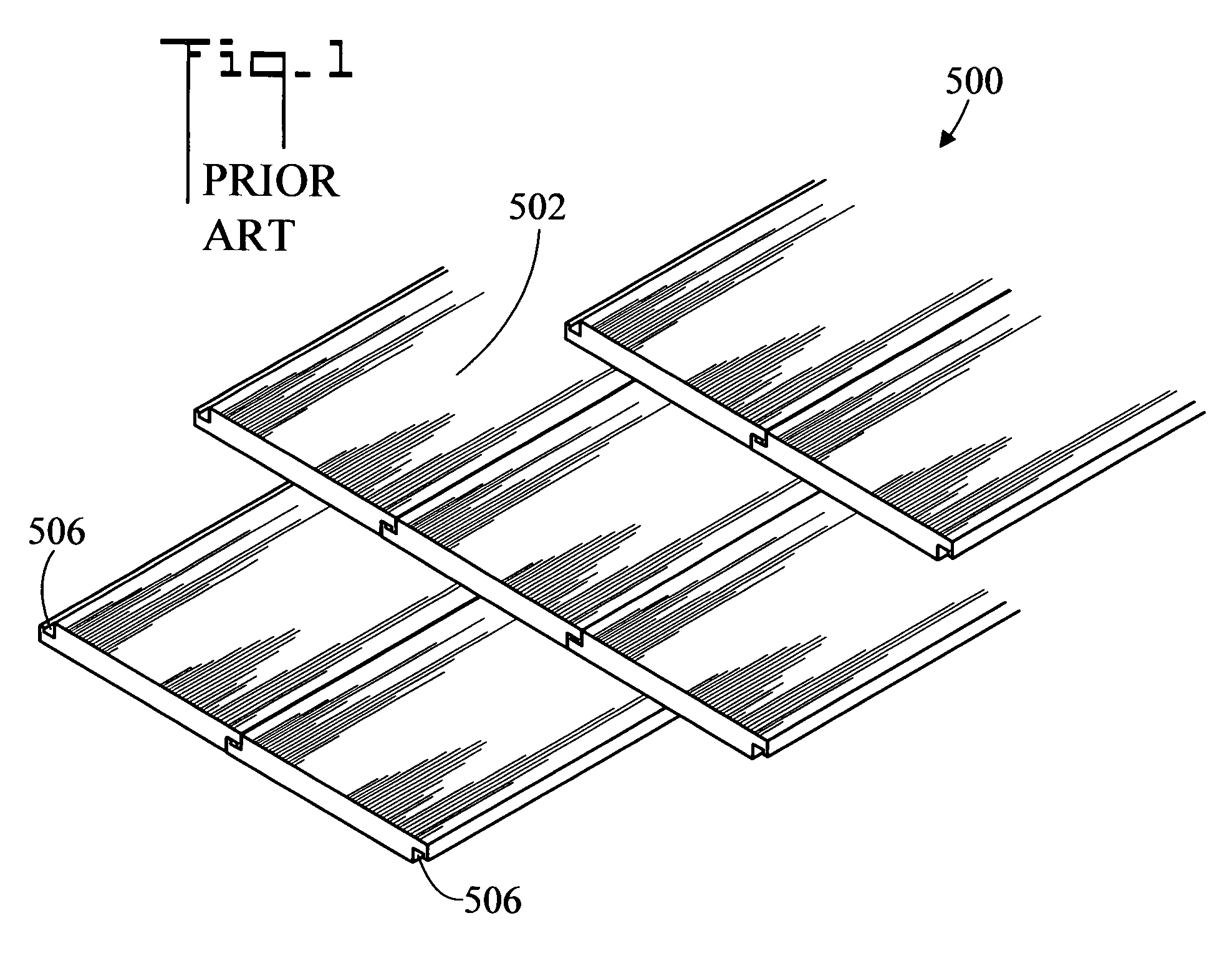
TECHNICAL FIELD[0001]The present invention pertains generally to roofs, and more particularly to a method and system for installing a stanchion on a tile roof while maintaining waterproof integrity.BACKGROUND OF THE INVENTION[0002]Many roofs comprise a plurality of individual overlapping roof tiles which are installed over a roof sheathing. With such tile roofs it is troublesome to install stanchions to support roof fixtures such as solar panel structures. The current method of adding a stanchion comprises removing several tiles, attaching a stanchion to the roof, waterproofing the stanchion at the subroof (sheathing), reinstalling the tile around the mount by cutting away the one or two tiles around the stanchion, and flashing the hole around the stanchion with metal flashing. An installation of a solar system usually requires multiple points of contact to comply with building codes. In many instances, it is easier and less expensive to actually remove an entire section of roof, an...

Claims


Application Information

Patent Timeline
IPC IPC(8): E04G23/00
CPCE04D1/30E04G23/00F24J2/5245E04D2001/307Y10T29/49739Y02E10/47Y10T29/49718Y10T29/49721Y10T29/49735Y02B10/20E04G23/0281F24S25/61E04D1/2916
Inventor WENTWORTH, STUART H.WENTWORTH, CLAUDIA H.
Owner WENCON DEV INC
Learn More