Suture lock

a suture lock and suture technology, applied in the field of surgical practice and procedures, can solve the problems of excessive scar tissue, inability to remove, and considerable stress on the part of surgeons performing such operations, and achieve the effect of quick and efficient manner

Inactive Publication Date: 2011-01-04
ANPA MEDICAL
View PDF88 Cites 101 Cited by
  • Summary
  • Abstract
  • Description
  • Claims
  • Application Information

AI Technical Summary

Benefits of technology

[0008]It is an object of the present invention to provide a suture lock that will sufficiently lock a suture in place in a quick and efficient manner. This novel design approach allows a single surgeon working in a laparoscopic environment to suture a surgical site with one or more suture...

Problems solved by technology

Surgeons performing such operations are under considerable stress because remote manipulation of the surgical instruments using a video screen for visualization, rather than seeing the site of the operation directly, requires the learning of a great many techniques that are radically different from those performed when the surgical site is open to view.
Such knots permanently fix a sut...

Method used


Image

  • Suture lock
  • Suture lock
  • Suture lock

Examples


Embodiment Construction

[0050]Although the disclosure hereof is detailed and exact to enable those skilled in the art to practice the invention, the physical embodiments herein disclosed merely exemplify the invention that may be embodied in other specific structure. While the preferred embodiment has been described, the details may be changed without departing from the invention.

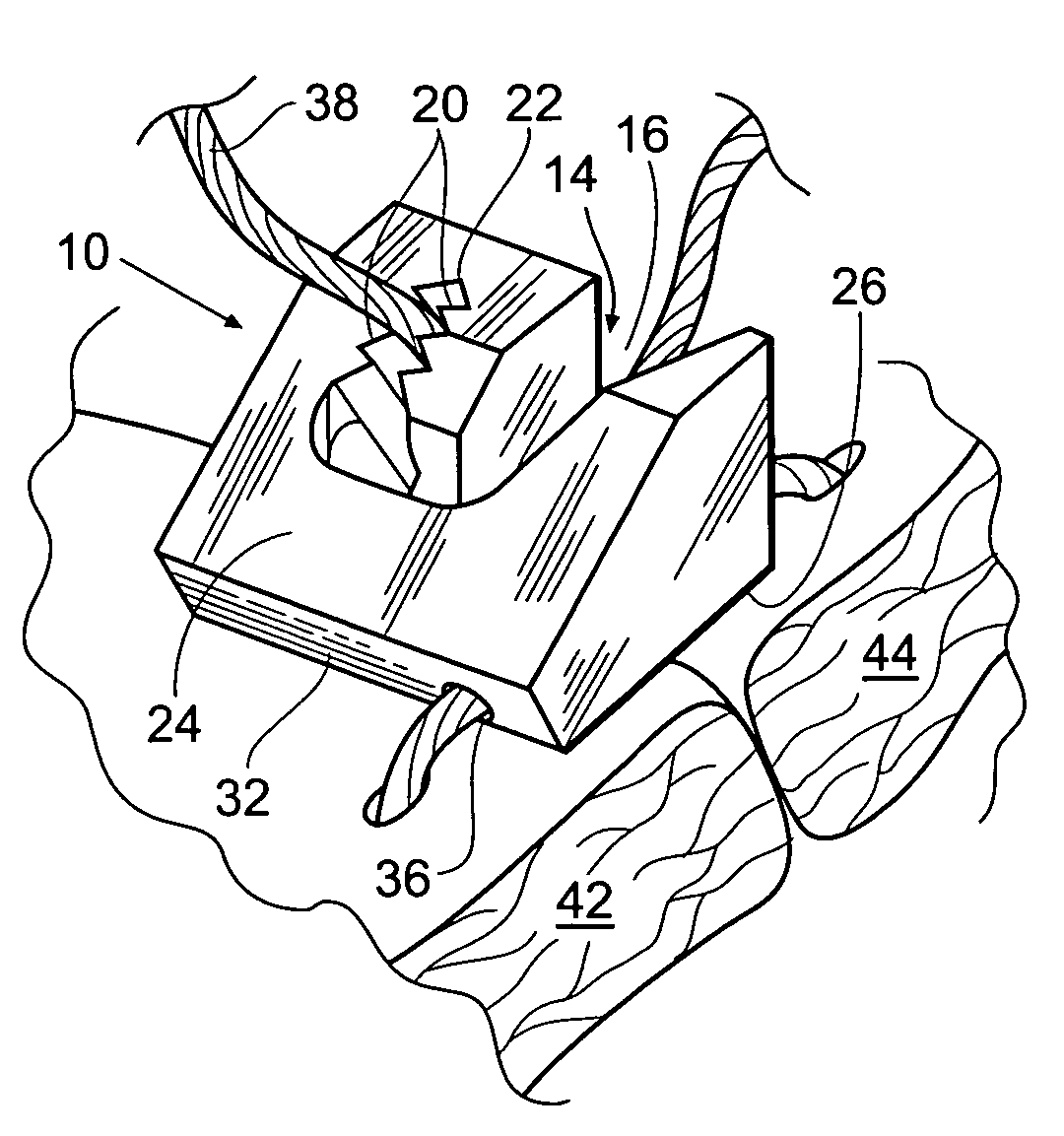
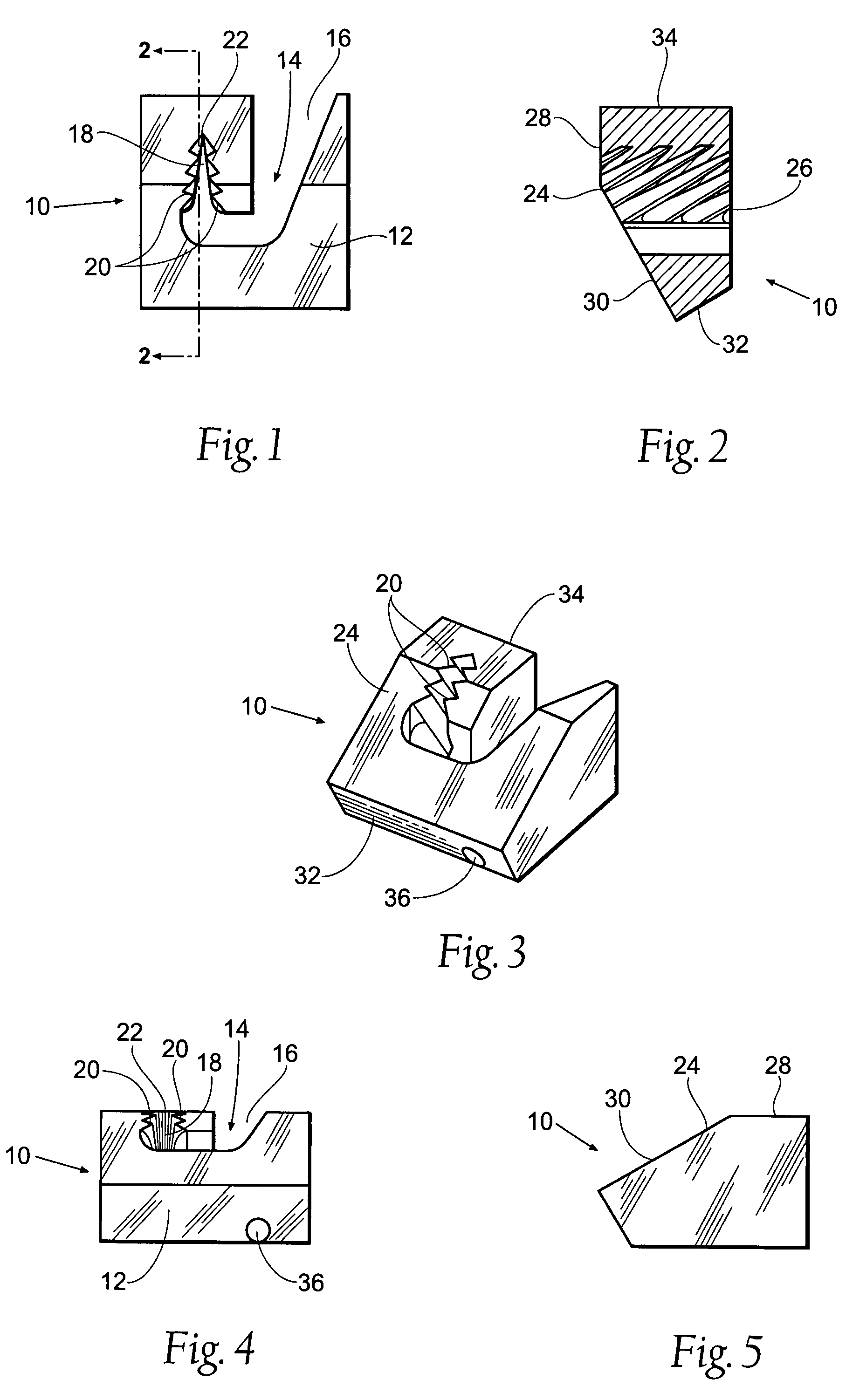
[0051]FIG. 1 depicts an overhead view of a suture lock 10 in accordance with the present invention. The suture lock has a main body 12, which provides support when a suture is fed into the suture lock 10. An elongated opening 14 having an open end 16 and a terminal end 18 is located within the body 12. The opening 14 preferably has a curved hook-shaped path, with the open end 16 being larger than terminal end 18. The open end 16 is preferably substantially larger than a suture thread that will be fed into the suture lock 10, thereby easing the process of feeding a suture thread into the suture lock 10, while the terminal end 18 is...


PUM


Abstract

A suture lock to be used with a suture thread. The suture lock comprises at least one passageway for receiving a suture thread, with the passageway having at least a portion of its length having a longitudinal side opening arranged to slidably receive the suture. The passageway is tapered inwardly and including an interior surface having inwardly converging teeth. The invention may also comprise a suture lock having an adjustable channel located within the suture lock. The channel may be adjusted between an open and a closed position, thereby allowing the suture to be secured. Translation of the suture itself may be utilized to adjust the positioning of the channel. The suture lock may contain a releasable device to retain the channel in multiple positions between the closed and open position.

Description

RELATED APPLICATION[0001]This application claims the benefit of co-pending provisional patent application Ser. No. 60 / 468,496, filed 7 May 2003.BACKGROUND OF THE INVENTION[0002]The need for this invention arises from surgical practice and procedures, particularly surgical practice and procedures using laparoscopic instruments. Utilizing laparoscopic instruments involves making two or more small incisions in the area of the surgical site. A laparoscopic video camera is inserted into one of the incisions to view the field of the operation inside the patient and laparoscopic surgical instruments are inserted in other incisions and manipulated from outside the patient's body using a video screen visualization, usually enlarged, to guide the work.[0003]Anything that can reduce the number of steps to be performed during surgery can markedly reduce the stress of the procedure, both on the patient and on the doctor. Reducing the number of steps will also reduce the time involved for the pro...

Claims


Application Information

Patent Timeline
IPC IPC(8): A61B17/04
CPCA61B17/0487A61B2017/00407A61B2017/0448A61B2017/045A61B2017/0454A61B2017/0456A61B2017/0464
Inventor LYONS, DAVID F.BREINING, PETER M.
Owner ANPA MEDICAL
Why Eureka
Try Eureka