Modular mold change system

a mold machine and module technology, applied in the field of injection molding machines, can solve the problems of wasting valuable time, reconnection is often unclean, and the process of reconnection is quite time-consuming, and achieve the effect of quick and efficient manner

Inactive Publication Date: 2006-11-30
INJECTNOTECH
View PDF11 Cites 28 Cited by
  • Summary
  • Abstract
  • Description
  • Claims
  • Application Information

AI Technical Summary

Benefits of technology

[0004] It is an object of the invention to provide an improved method and apparatus which allows for removal and installation of mold components in a quick and efficient manner.

Problems solved by technology

The process of reconnection is quite time consuming.
Furthermore, such reconnection is often uncleanly due to necessity of disconnecting water hoses.
Furthermore since all services are disconnected and reconnected, water drained, valuable time is lost waiting for the mold and machine to heat up again once the mold is installed.
Furthermore, known support mechanisms which secure the molds within the machine platen of the mold machine, are not typically adaptable to accommodate mold or machines of different sizes and / or require hand loading of heavy parts once the mold is moved in between the machine platens.

Method used


Image

  • Modular mold change system
  • Modular mold change system
  • Modular mold change system

Examples


Embodiment Construction

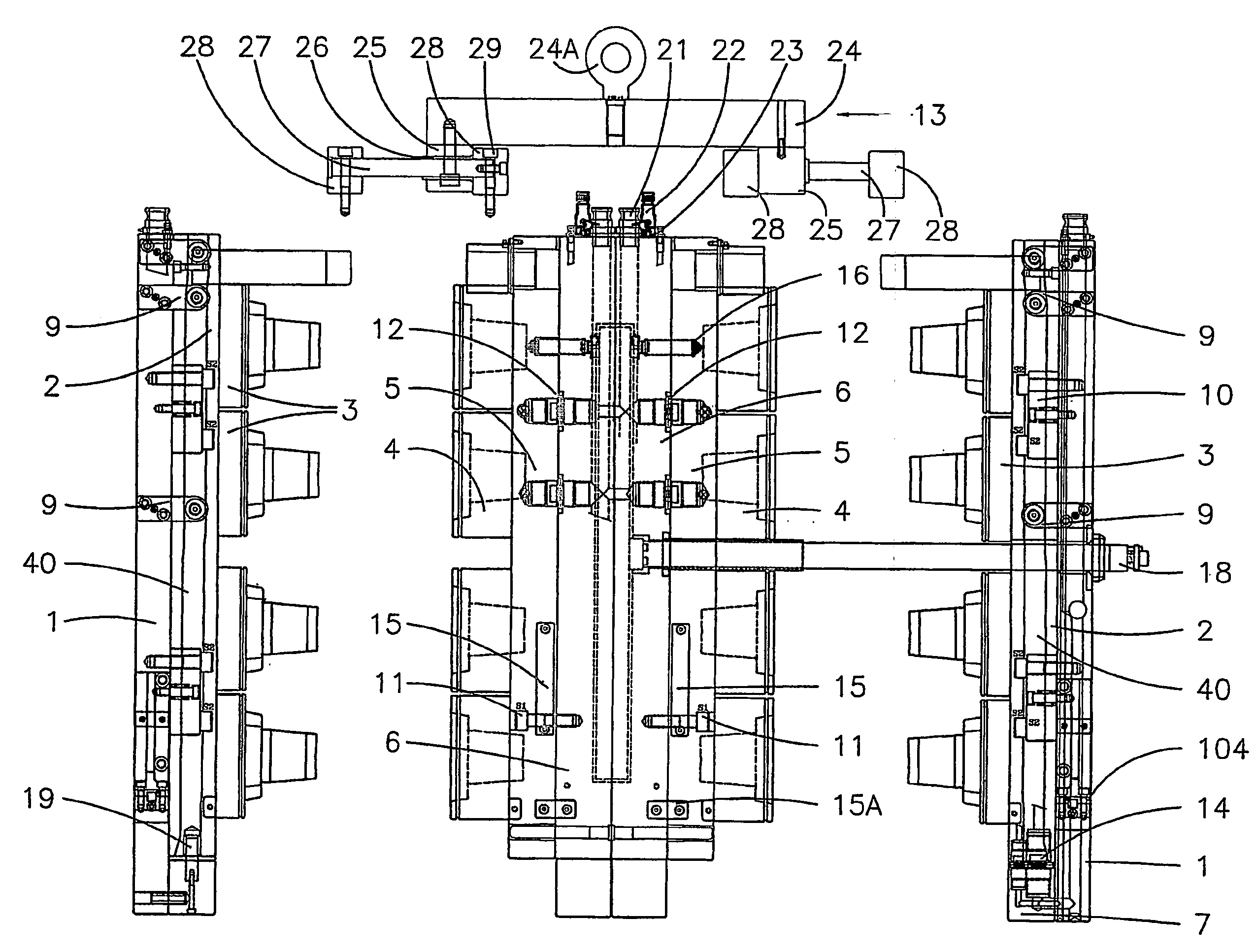
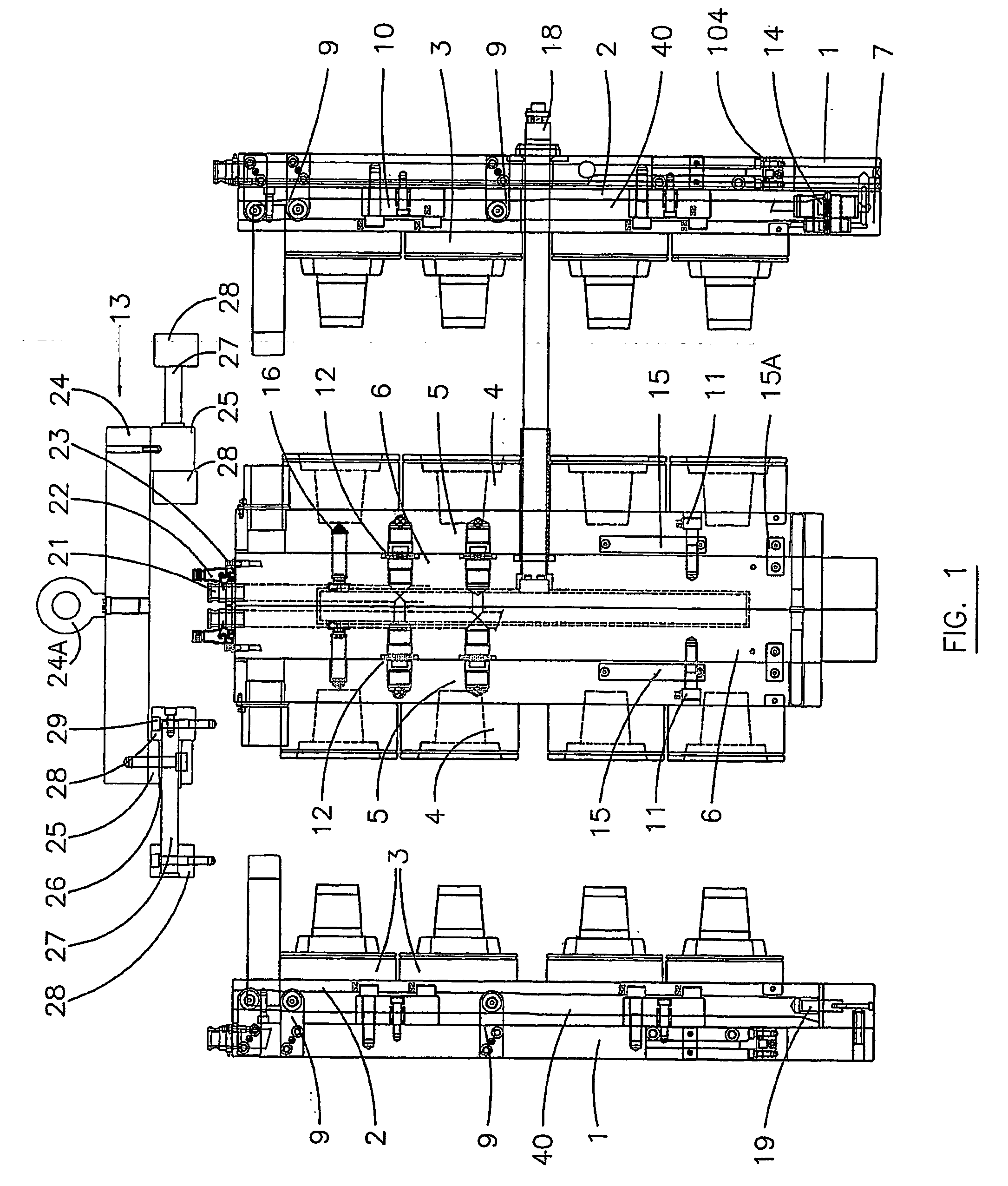
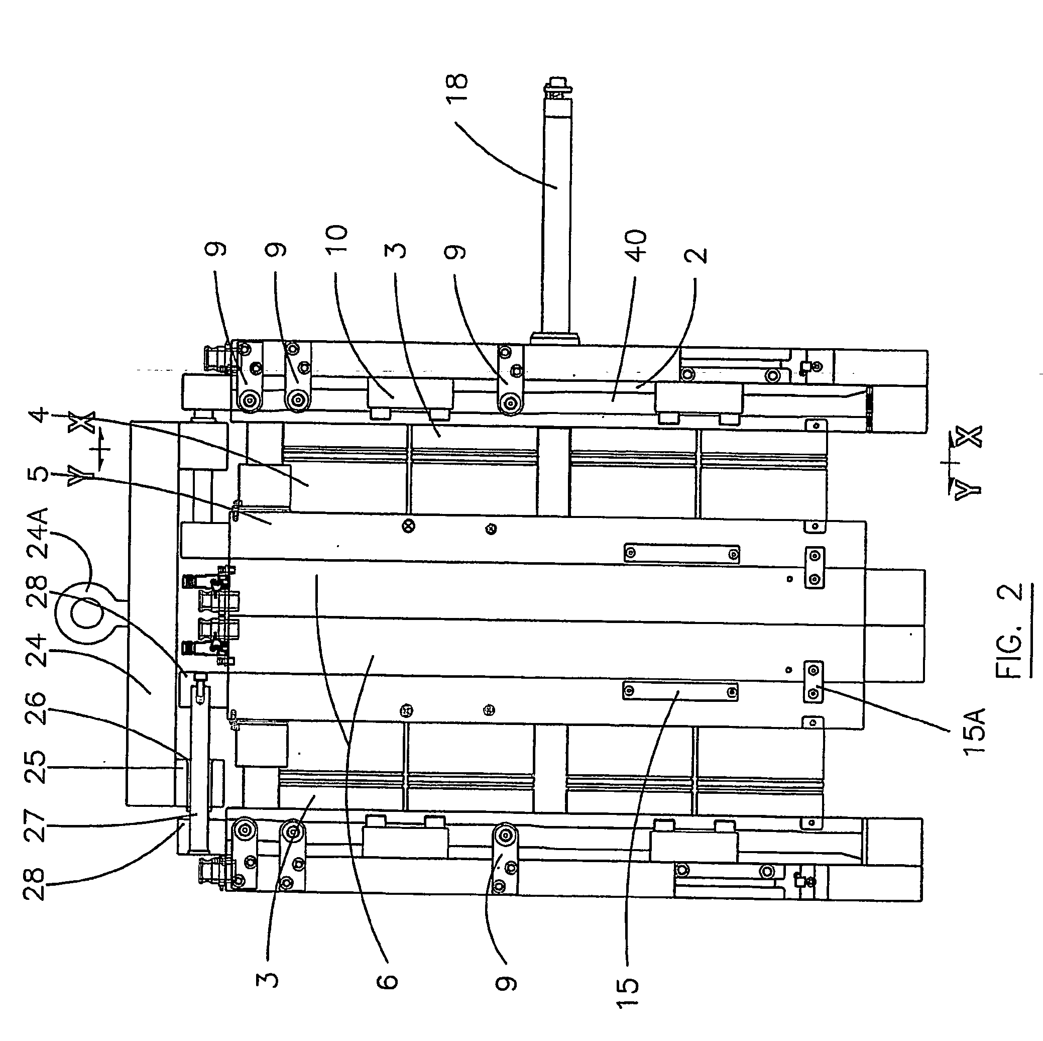
[0058] An example embodiment of an aspect of the invention will now be described, by way of example, with reference to the accompanying drawings, particularly FIGS. 1 to 6. The drawings show an embodiment of the mold change system (also referred to as an MMC) in accordance with the invention, used with a stack mold having a 2×8 (16 cavity) arrangement, used for molding thin walled containers designed for consumer use. It should be understood that the system may be utilized with a single face mold system and may be used to form any shape or type of article.

[0059] The following is a detailed description of how an embodiment of an MMC system allows the quick change over of mold products (i.e. cavity and core plates with attached inserts) with all service (water, air and heats) left intact, while the mold plates are changed. This MMC system may be utilized with single face and stack molds systems.

[0060] As shown in FIGS. 1 to 6, the mold or mold set (also referred to as an MMC) in the...


PUM

PropertyMeasurementUnit
shapeaaaaaaaaaa
dimensionsaaaaaaaaaa
lengthaaaaaaaaaa

Abstract

A method of removing components of an injection mold machine having a core assembly and a cavity assembly, the method including the steps of: (a) moving the core assembly and the cavity assembly into a closed position whereat a cavity insert and a core insert are mated together; (b) securing a core plate to a cavity plate, thereby forming a mold module; (c) releasing a securing means which secures the cavity plate to a manifold plate; (d) opening the mold from the closed position, until a first cavity plate disengages the manifold plate and all connections thereto, (e) releasing a securing means which secures the core plate to a master core plate; and (f) lifting the mold module in a direction perpendicular to a direction of motion between the open and closed position, the module being guided in the perpendicular direction by the guide means.

Description

FIELD OF THE INVENTION [0001] This invention relates to injection molding machines and in particular to a system for changing components of the mold machine. BACKGROUND OF THE INVENTION [0002] It is known to provide systems which attempt to achieve the quick and efficient changing of mold machine components. A typical mold change system involves the removal of the complete mold (or mold set) including core plates, manifold plate, cavity plate and attached inserts from the injection mold machine in a manner which requires the disconnecting of water hoses, airlines, and electrical connectors necessary for proper operation of the machine. In such prior art systems, before disconnecting all these services, the mold must be drained of water and the hot-runner switched off. The mold is typically then unclamped and hoisted out of the molding machine, typically with an overhead crane. When installing a new mold in the injection machine, in a known manner all the above-mentioned services mus...

Claims


Application Information

Patent Timeline
Patent Type & Authority Applications(United States)
IPC IPC(8): B23P19/00B29C33/30B29C45/17B29C45/32
CPCB29C33/0088B29C45/1742Y10T29/49815B29C45/32B29C2045/326B29C45/1756
Inventor CICCONE, VINCE
Owner INJECTNOTECH
Why Eureka
Try Eureka