Wavefront analysis method involving multilateral interferometry with frequency difference

a wavefront analysis and multi-lateral interferometry technology, applied in the field of analysis of the wavefront of light beams, can solve the problems of inability to analyze divided wavefronts, inability to simultaneously implement one single wavelength, prohibitive limitation, etc., and achieve the effect of estimating the error

Active Publication Date: 2011-01-04
OFFICE NAT DETUDES & DE RECH AEROSPATIALES
View PDF20 Cites 4 Cited by
  • Summary
  • Abstract
  • Description
  • Claims
  • Application Information

AI Technical Summary

Benefits of technology

[0031]A two-dimensional diffraction grating makes it possible to observe in an observation plane an interferogram characterizing the wavefront of the beam to be analyzed.
[0048]As the increase rates of a wavefront are proportional to the differences in level, while selecting λ2 sufficiently close to λ1, it thus becomes possible to measure the increase rates whatever their amplitudes.
[0067]According to an alternative, the two-dimensional diffraction grating (GR) allows for extracting three sub-beams, the observation of which in a distant field forms three spots positioned according to an isosceles triangle, thereby defining three privileged directions, so as to rebuild the wavefront and estimate the error on the measurement from the measurement itself.

Problems solved by technology

Such a device, generally based on a Michelson type interferometer, is chromatic and can only simultaneously implement one single wavelength.
In the usual usage mode, the so-called “Shack-Hartmann” wavefront analyzers do not allow to analyze divided wavefronts.
Such a limitation is prohibitory for the above-mentioned applications.

Method used


Image

  • Wavefront analysis method involving multilateral interferometry with frequency difference
  • Wavefront analysis method involving multilateral interferometry with frequency difference
  • Wavefront analysis method involving multilateral interferometry with frequency difference

Examples


Embodiment Construction

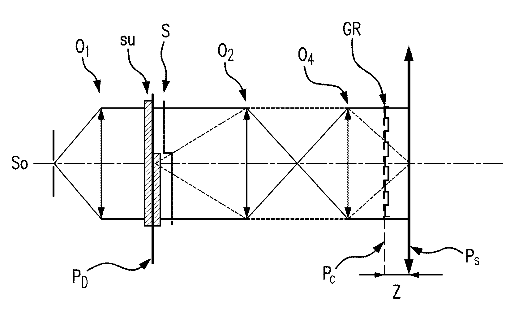
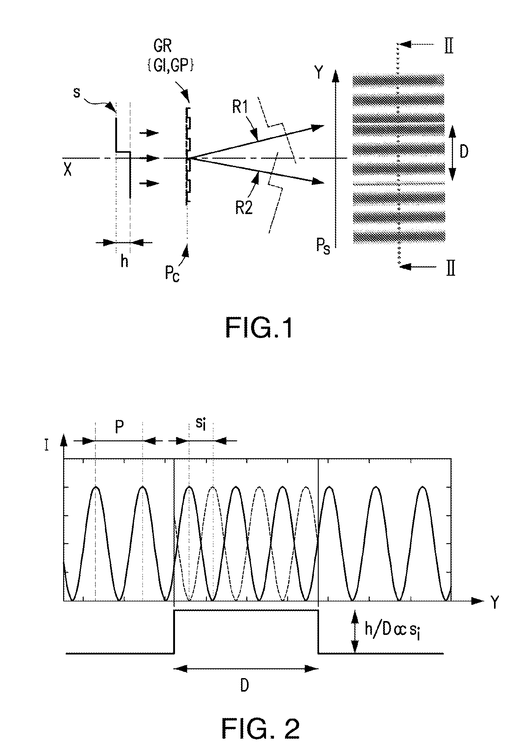
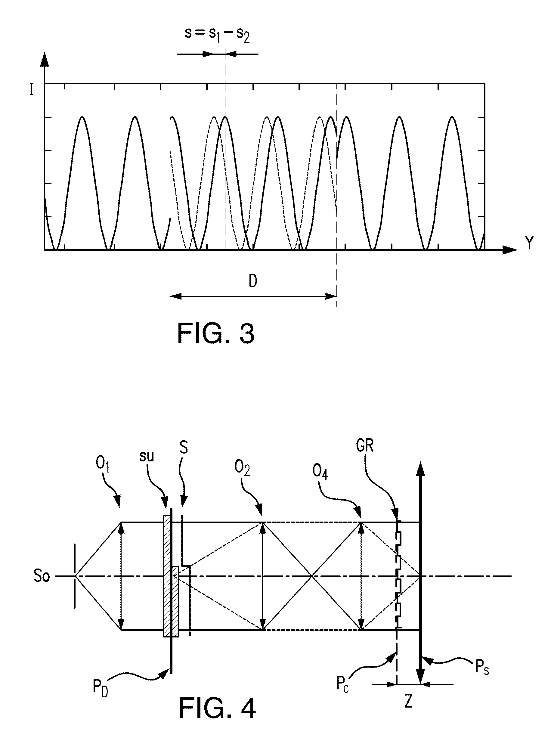
[0078]On FIG. 1, in order to illustrate, as simply as possible, the present invention, the incident beam with a wavelength λi propagating according to the axis X has a wavefront S with two parts having a difference in level with a height h. The two-dimensional grating GR is positioned in a plane Pc preferably perpendicular to the axis X.

[0079]Still with a view to simplification, only one pair of sub-beams is taken into consideration. The sub-beams propagate according to the two particular directions R1 and R2, corresponding to two different orders of diffraction, forming therebetween the privileged rocking angle and defining, in the observation plane Ps, the lateral shear D. The plane Ps is parallel to the plane Pc and it thus in turn preferably perpendicular to the axis X.

[0080]Thus, the interferogram observed in the plane Ps is an elementary interferogram comprising quasi-rectilinear fringes, perpendicular to the direction Y, referred to as the privileged direction.

[0081]As the wa...


PUM


Abstract

The method comprises positioning a diffraction grating with a two-dimensional meshing on the path of the beam to be analyzed and processing at least two interferograms of at least two different colors, each interferogram being obtained in a plane from two sub-beams with different diffraction orders. The invention can be used to analyze and correct divided wavefronts.

Description

REFERENCE TO RELATED APPLICATIONS[0001]The present application is a continuation of the PCT International Application No. PCT / FR2007 / 050810 filed Feb. 15, 2007, which is based on the French Application No. 0601362 filed Feb. 16, 2006.BACKGROUND OF THE INVENTION[0002]1. Field of the Invention[0003]This invention relates to the analysis of the wavefront of a light beam.[0004]2. Description of the Prior Art[0005]Such a type of analysis makes it possible to test optical elements, as well as to qualify optical devices. It also allows for the study of non-directly measurable physical phenomena, such as optical index variations within turbulent media that can be encountered when crossing the earth atmosphere, as well as in a blowing vein. Numerous other applications could be contemplated such as metrology and the control of traditional or intense lasers.[0006]The type of analysis of a wavefront according to this invention is based on the use of a diffraction grating positioned on the path ...

Claims


Application Information

Patent Timeline
Patent Type & Authority Patents(United States)
IPC IPC(8): G01B9/02
CPCG01J9/02G01J2009/0226G01B9/02
Inventor PRIMOT, JEROMEVELGHE, SABRINAGUERINEAU, NICOLASHAIDAR, RIADTAUVY, MICHEL
Owner OFFICE NAT DETUDES & DE RECH AEROSPATIALES
Why Eureka
Try Eureka