Method of and system for determining distances between loudspeakers

a distance measurement and distance technology, applied in the direction of direction finders, loudspeaker enclosure positioning, instruments, etc., can solve the problems of difficult setup for many users, speaker placement might be incorrectly placed about the room, and significantly diminish the quality of the combined audio and video experience, etc., to achieve the effect of convenient and economical

Inactive Publication Date: 2011-01-04
KONINKLIJKE PHILIPS ELECTRONICS NV
View PDF20 Cites 11 Cited by
  • Summary
  • Abstract
  • Description
  • Claims
  • Application Information

AI Technical Summary

Benefits of technology

[0009]Therefore, an object of the present invention is to provide an easy and economical way of automatically measuring the distances between loudspeakers of a sound system during operation of the sound system, which can be carried out at any time without effecting normal operation and without disturbing the user.
[0013]A clear advantage of the method according to the invention is that the measurement of the distances between the loudspeakers can take effect completely automatically, without being noticed in any way by the user, and can be carried out at any time, regularly or intermittently, so that any deliberate or accidental re-arrangement of the loudspeakers can be detected and compensated for.
[0022]The amplitude of the noise contribution of the test signal is of necessity very low compared to the host audio signal with which it is combined. Therefore, in a further preferred embodiment of the invention, the step of processing the detected combined signal comprises accumulation of the received combined signal, by sampling and storing the detected combined signal in a buffer with the same length as a period of repetition of the test sequence. In this way, the noisy test signal accumulates, whilst the host sound signal can be essentially averaged out. The step of accumulation therefore increases the ratio of the noise to the host, so that the noise contribution of the test signal can be identified more easily. The level of the noisy test signal can therefore easily be kept so low as to be absolutely imperceptible to the listener.
[0028]The information regarding the relative positions of the loudspeakers of the group of loudspeakers, as derived using a method according to the invention, can be used to modify the sound signals before they are issued by the loudspeakers in order to automatically configure the loudspeakers. For example, by “weighting” or increasing the amplitude of a line input to a speaker, it is possible to compensate, for example, for an overly large distance between this speaker and the listener. Equally, a number of sound channels might be weighted and mixed together to correct an erroneous loudspeaker setup. For example, it can be determined, using the method according to the invention, whether or not a loudspeaker is even connected. A missing loudspeaker can then be “replaced” by mixing the sound channel intended for this loudspeaker with the sound channel for one or more other loudspeakers. The information can be used to inform the user in some appropriate way, for example by showing a message in a display area of a home entertainment system. Furthermore, the method according to the invention can be used to determine whether the polarity of the loudspeaker connections or leads is correct or not. In the case of an incorrect connection, the sign—positive or negative—of the first peak of the impulse response will be different from the sign of the impulse response of a loudspeaker with correctly connected leads. An incorrect, inverse polarity can be corrected by, for example, inverting the appropriate sound channel for the line input to this speaker. The invention thus provides a number of powerful and practical ways of improving the quality of sound emanating from the loudspeakers.

Problems solved by technology

In practice it remains difficult for many users to perform the setup correctly, so that the speakers might be incorrectly placed about the room with respect to the television set.
For example, the user might mistakenly connect the left surround speaker where the right surround speaker should be connected, or might entirely forget to connect a loudspeaker.
Such an error significantly diminishes the quality of the combined audio and video experience, since the perceived sounds can appear to come from the “wrong” direction in relation to that which is seen on screen.
The result of such configuration errors is that some of the listening effects might fail to be reproduced correctly, resulting in dissatisfaction on the part of the user of the sound system.
Even if the loudspeakers are correctly connected, their placement about the room might still not satisfy requirements for the reproduction of the surround sound effects and a “sweet spot”—the area within a group of loudspeakers in which the sound is heard at its best.
For example, the loudspeakers might be placed too far apart or too close together.
Ultimately, it can be seen that the correct connection and placement of loudspeakers for a surround sound system is quite often beyond the capabilities of many of the owners of such systems.
Should the sensor be misplaced at some point in time, the user can no longer initiate an optimisation of the loudspeaker sound.
This proposed system offers no solution in the event of incorrect or missing loudspeaker connections.
However, a major disadvantage of this approach is that the test signal of the proposed system is issued in a separate setup procedure and can be heard by the user.
However, since the user would probably have to consult the manual to determine the input command, he might not be inclined to carry out the configuration at all.
For many consumers, such configuration systems are simply too complicated and are perceived to be annoying, with the result that the user does not avail of them, or does not carry out the steps correctly, ultimately resulting in his dissatisfaction with the sound system.

Method used


Image

  • Method of and system for determining distances between loudspeakers
  • Method of and system for determining distances between loudspeakers
  • Method of and system for determining distances between loudspeakers

Examples


Embodiment Construction

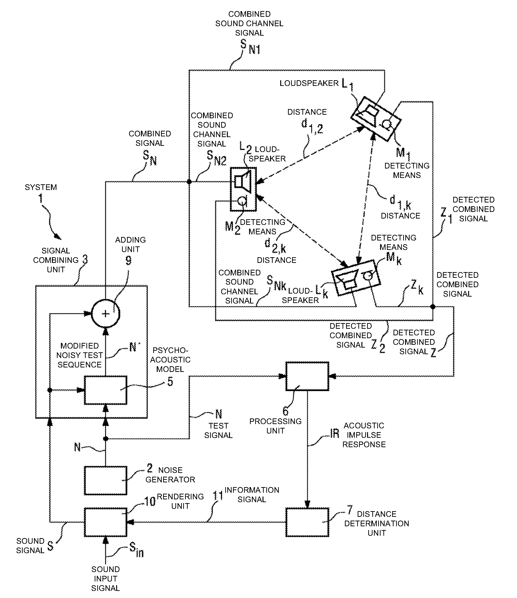
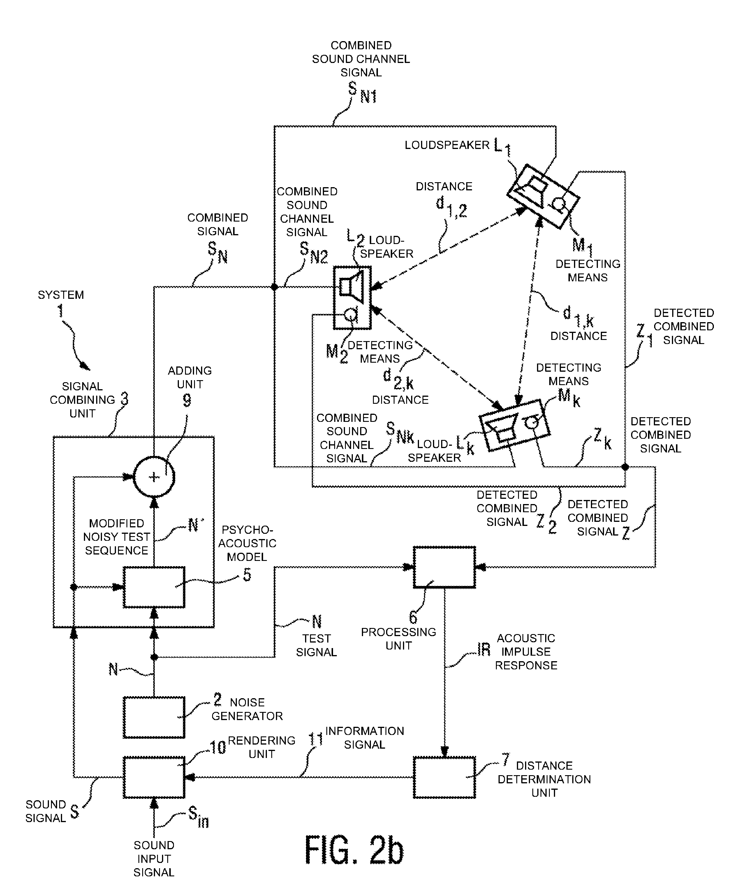
[0042]In the drawings, like numbers refer to like objects throughout.

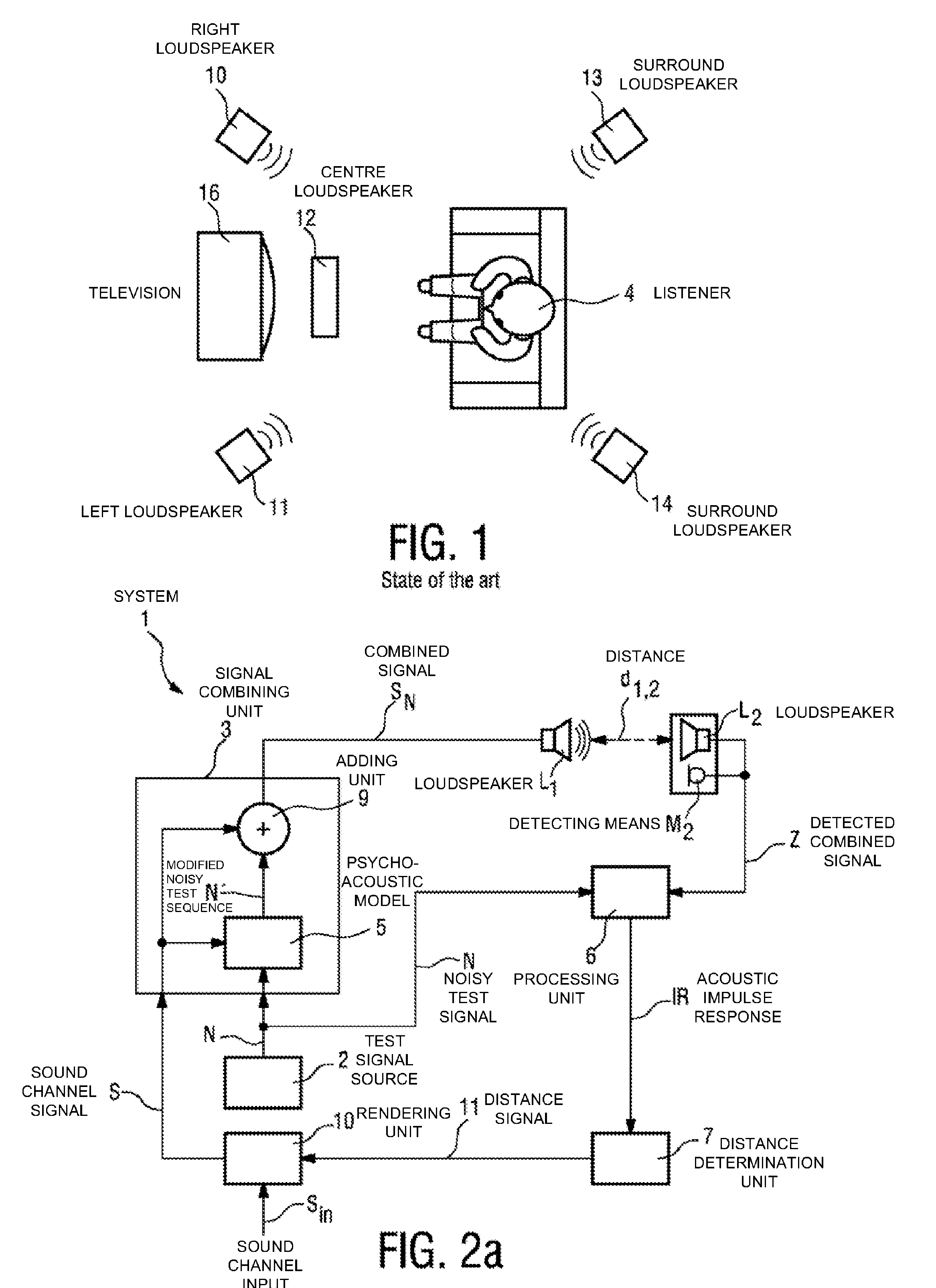
[0043]FIG. 1 shows a typical loudspeaker setup for an audio or home entertainment system which comprises, in this example, a television 16 and a number of loudspeakers such as a left loudspeaker 11 and a right loudspeaker 10 and a pair of surround loudspeakers 13, 14 distributed about the room. A centre loudspeaker 12 is shown, for the purpose of illustration, at a distance from the television 16, even though such a centre loudspeaker 12 is generally located below the television 16. The television 16 itself might also be equipped with one or more loudspeakers, not shown in the diagram. A listener 4 is shown seated more or less centrally to the loudspeakers 10, 11, 12, 13, 14. Evidently, the loudspeakers 10, 11, 12, 13, and 14 can have been placed at any position in the room, often determined by decorating or physical constraints. Furthermore, the listener 4 need not be seated at a central position. Such a home ente...


PUM


Abstract

The invention describes a method of determining the distance (d12) between two loudspeakers (L1, L2), wherein the method comprises the steps of providing a test signal (N), combining the test signal (N) with a sound signal (S) to give a combined signal (SN) in which the test signal is imperceptible to a listener (4), and issuing the combined signal (SN) by means of a first loudspeaker (L1). The combined signal (SN) is detected by a detecting means (M2) associated with the second loudspeaker (L2) and processed to obtain an acoustic impulse response (IR), which is used to determine the distance (d1,2) between the first loudspeaker (L1) and the second loudspeaker (L2). The invention further describes a system (1) for determining the distance (d1,2) between two loudspeakers (L1, L2) and an acoustic sound system, comprising a number of loudspeakers (L1, L2, . . . , Lk) for reproduction of multi-channel sound, and a system (1) for determining the distances (d1,2, d2,3, . . . , dk-i,k) between the loudspeakers (L1, L2, . . . , Lk) in order to automatically configure the loudspeakers (L1, L2, . . . , Lk) for that acoustic sound system.

Description

FIELD OF THE INVENTION[0001]The invention relates to a method of determining the distance between two loudspeakers, and to a system for determining the distance between two loudspeakers.[0002]The invention also relates to a method of determining the relative positions of the loudspeakers of a group of loudspeakers and to a method of automatic configuring of a group of loudspeakers.[0003]Furthermore, the invention relates to an acoustic sound system.BACKGROUND OF THE INVENTION[0004]Present-day surround sound systems often feature a number of loudspeakers, which should be positioned strategically around a listener in a room so that the listener is given the impression that the sound emanating from the loudspeakers originates from all around, or that a particular sound such as a voice originates from a virtual source, e.g. from a point to the left of the listener. These sound effects rely on a correct positioning of the loudspeakers, since it is the interaction of the lobes of sound or...

Claims


Application Information

Patent Timeline
Patent Type & Authority Patents(United States)
IPC IPC(8): G01S3/80
CPCH04S7/301H04R2205/024H04R2400/01
Inventor VAN LEEST, ADRIAAN JOHANSCHOBBEN, DANIEL WILLEM
Owner KONINKLIJKE PHILIPS ELECTRONICS NV
Why Eureka
Try Eureka