Device for separating impurities from the lubricating oil of an internal combustion engine

a technology of lubricating oil and internal combustion engine, which is applied in the direction of engine lubrication, centrifuges, stationary filtering elements, etc., can solve the problems of affecting the lubrication of the engine, the inability to hold the intermediate cap sufficiently firmly, and the inability to remove the intermediate cap from the lower part of the housing, so as to achieve convenient, fast and clean disassembly and assembly. , the effect of easy and fast disa

Inactive Publication Date: 2011-01-11
HENGST WALTER
View PDF13 Cites 1 Cited by
  • Summary
  • Abstract
  • Description
  • Claims
  • Application Information

AI Technical Summary

Benefits of technology

[0005]Therefore, the present invention aims at creating a device of the aforementioned type, which obviates the drawbacks described above and which particularly allows disassembly and assembly to be carried out in an easier, faster and cleanlier manner, especially in connection with the replacement of the filter element and / or the centrifuge rotor.

Problems solved by technology

Obviously, disassembly and assembly of this known device are relatively complicated and troublesome.
Apart from operating personnel getting their hands dirty, this poses the further problem that it is difficult to hold the intermediate cap sufficiently firmly because of its oily surface.
As a result, it is even more difficult to pull out the intermediate cap from the lower part of the housing against the developing frictional forces and against a possibly present vacuum.

Method used


Image

  • Device for separating impurities from the lubricating oil of an internal combustion engine
  • Device for separating impurities from the lubricating oil of an internal combustion engine
  • Device for separating impurities from the lubricating oil of an internal combustion engine

Examples


Embodiment Construction

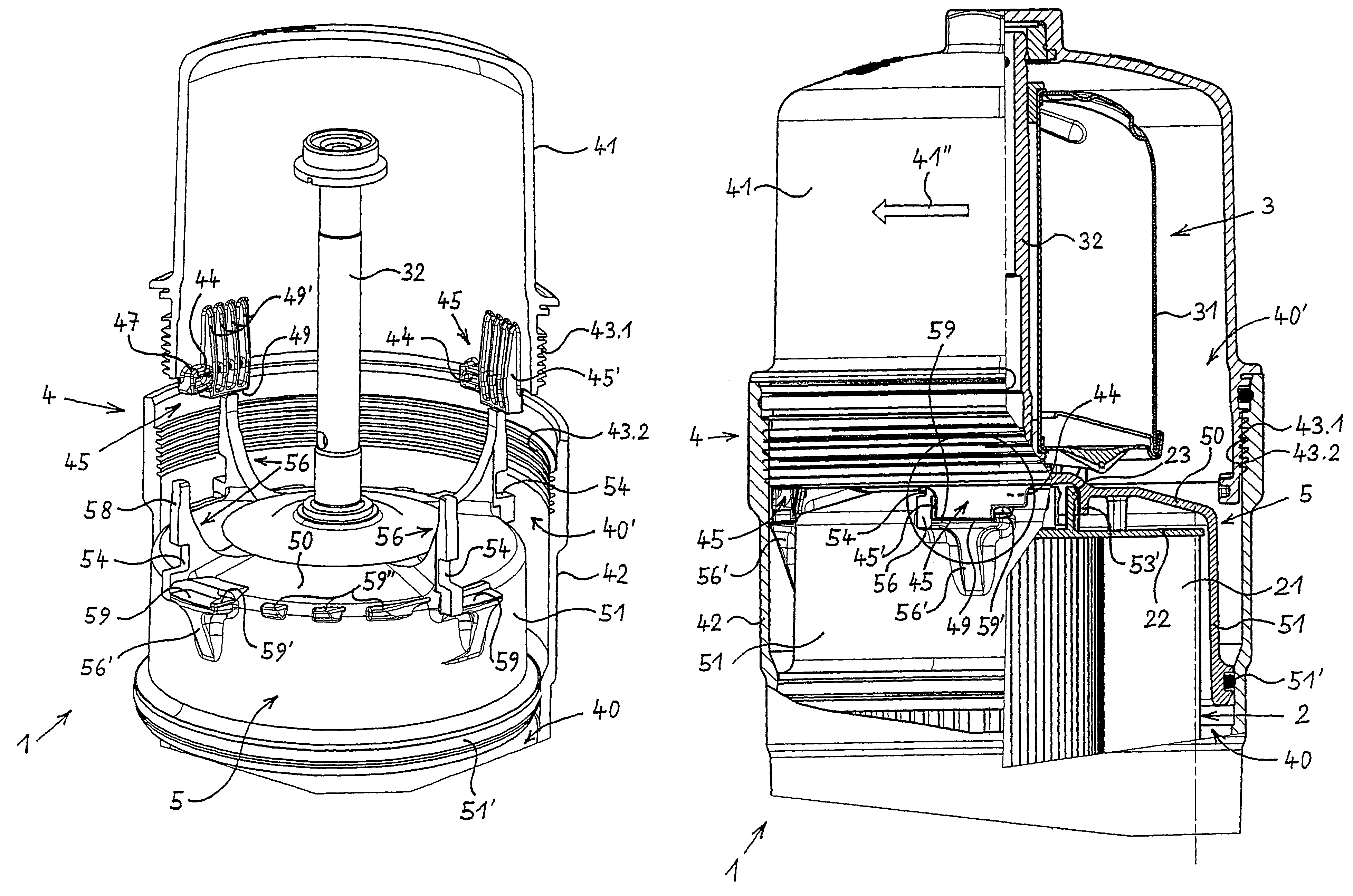
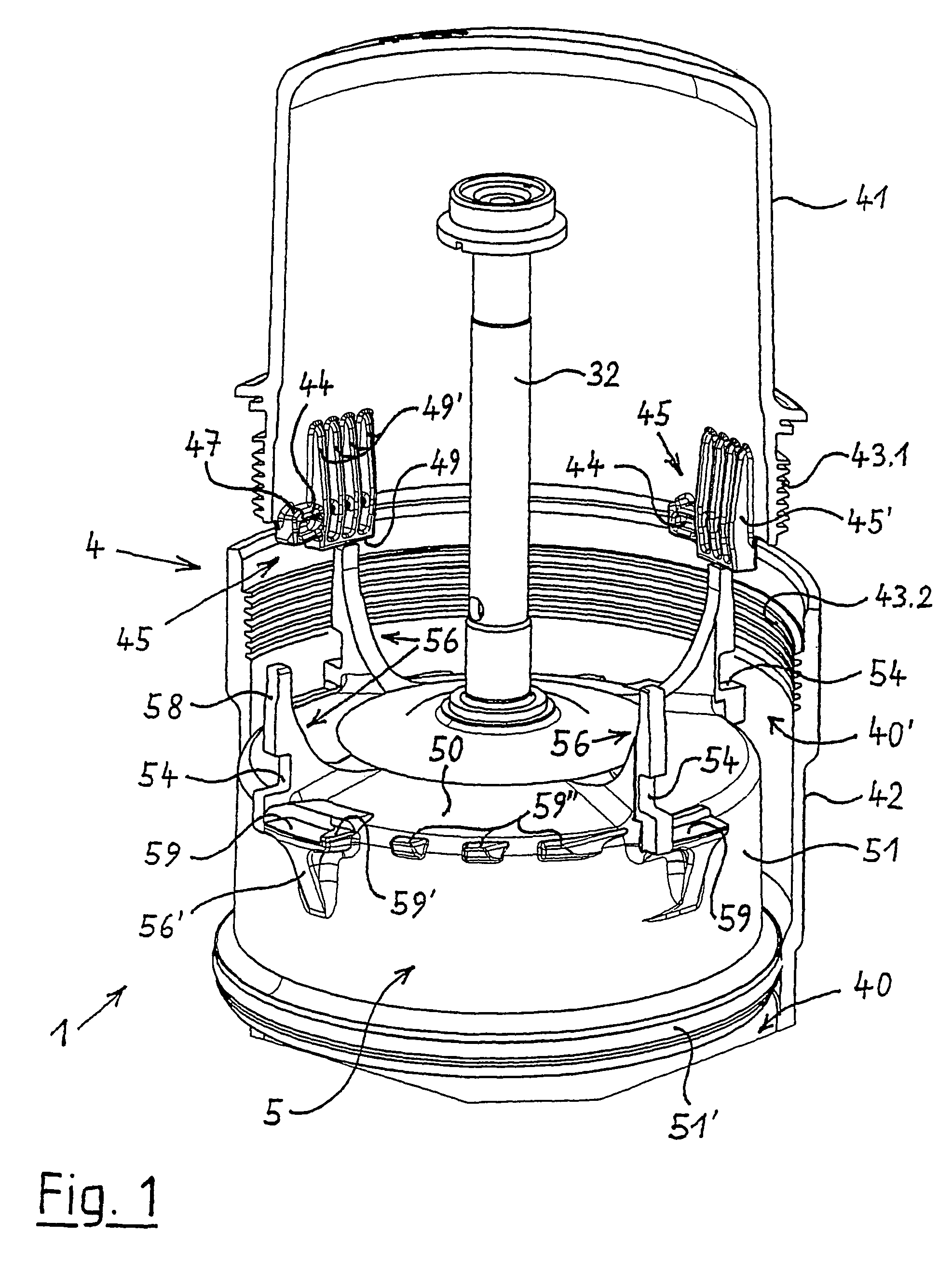
[0073]As shown in FIG. 1 of the drawing, the represented first exemplary embodiment of the device 1 for separating impurities from the lubricating oil of an internal combustion engine comprises a housing 4 that is formed by a lower stationary housing part 42 and an upper screw cap 41. The screw cap 41 can be screwed into the stationary housing part 42 by means of a threaded connection 43.1, 43.2 that is sealed by a sealing ring, wherein the screw cap 41 is shown in FIG. 1 in a state where it has been rotated and loosened completely.

[0074]A filter element 2 that is not shown here (cf. FIG. 3) is arranged in a lower part of the housing 4. A centrifuge 3 (cf. FIG. 3), only one rotor axle 32 of which is shown here for reasons of clarity, is provided flush with the filter element 2 in the upper part of the housing 4 above said filter element 2, wherein a centrifuge rotor can be pivoted onto said rotor axle 32.

[0075]The interior region of the housing 4 is subdivided in a lower region 40 a...


PUM

PropertyMeasurementUnit
axial tractive forcesaaaaaaaaaa
compressive forcesaaaaaaaaaa
tractive forcesaaaaaaaaaa

Abstract

The invention relates to a device for separating impurities from the lubricating oil of an internal combustion engine. The device comprises a filter insert on the bottom and a centrifuge thereabove that is provided with a rotor which is driven by means of penetrating lubricating oil. The filter insert and the centrifuge are disposed on top of each other in a common two piece housing that is closed during operation of the device and encompasses a removable top screw cap and a fixed bottom housing part. A removable intermediate lid is positioned between the filter insert and the centrifuge within the housing. The centrifuge, the intermediate lid, and the filter insert can be removed from the housing in the open state thereof. Furthermore, the screw cap and the intermediate lid of the device are provided with detachable connecting members which engage with each other and transmit axial tractive forces or axial tractive and compressive forces.

Description

BACKGROUND OF THE INVENTION[0001]The present invention relates to a device for separating impurities from the lubricating oil of an internal combustion engine, said device comprising a filter element at its bottom and, on top of said filter element, a centrifuge with a rotor drivable by means of lubricating oil flowing therethrough, wherein said filter element and said centrifuge are arranged, one above the other, in a common two-piece housing that is closed during operation of the device and comprises a removable upper screw cap and a stationary lower housing part, wherein a removable intermediate cap is arranged in the housing between said filter element and said centrifuge, and wherein said centrifuge, said intermediate cap and said filter element can be removed from the housing while the latter is in its open state.[0002]A device of the aforementioned type has been disclosed in DE 43 06 431 C1. If the screw cap, as a removable part of the housing of this known device, is rotated...

Claims


Application Information

Patent Timeline
Patent Type & Authority Patents(United States)
IPC IPC(8): B04B9/06B01D29/21B01D35/30B01D36/04B04B5/00B04B7/02F01M11/03
CPCB01D29/21B01D35/30B01D36/045B04B7/02F01M11/03B04B5/005B01D2201/40F01M2001/1057F01M2001/1035B01D36/04B04B5/00B04B7/00
Inventor BAUMANN, DIETER
Owner HENGST WALTER
Why Eureka
Try Eureka