Eureka AIR delivers breakthrough ideas for toughest innovation challenges, trusted by R&D personnel around the world.

Method for monitoring a graphical user interface on a second computer display from a first computer

a graphical user interface and computer technology, applied in the field of computer systems, can solve the problems of inability to monitor the graphical user interface on the second computer display from the first computer, the sensitivity of the environment, and the generation of an enormous amount of heat, and achieve the effects of simple and quick execution of operations, low cost, and convenient us

Active Publication Date: 2011-01-11
EGGPLANT SOFTWARE INC
View PDF86 Cites 33 Cited by
  • Summary
  • Abstract
  • Description
  • Claims
  • Application Information

AI Technical Summary

Benefits of technology

[0016]A first object of the invention is to enable the execution of a plurality of user inputs directly through the computer system while responding to a video display. A second object of the invention is to enable the control of actions within the computer based upon the display. Another object of the present invention is to provide this capability using high level controls and commands that are intuitive and readily used. A further object of the invention is to enable this interaction and control to be instituted remotely through a communications interface through common Internet connection. Yet another object of the present invention is to enable both hardware and software developers to thoroughly test and evaluate the performance and operation of their developments and enhancements rapidly and with only minimal expense. An even further object of the invention is to permit a network or systems administrator to reliably, simply and quickly execute operations within an enterprise systems network, preferably without having to physically visit each of the computing devices within the network, and which would have been heretofore conducted with more time consuming, difficult and less reliable techniques.

Problems solved by technology

These early machines were massive structures using many vacuum tubes, the result of which was the generation of an enormous amount of heat, and an associated sensitivity to environment.
With these massive structures, all processing was performed centrally at this main computer, owing to the substantial expense required for isolation and environmental control.
While remote communications with a computer system were sometimes used, the use was extremely infrequent and necessarily limited owing to the poor communications capability available at the time.
These limitations of the need for environmental control and lack of adequate communications capability each persisted for several decades.
The waiting queues for these technical support personnel were notoriously long, with on-hold waits longer than an hour commonplace.
This arrangement was clearly less than optimum, requiring many times the effort that would have been required for the support personnel or a technician to directly diagnose and resolve the problem.
Nevertheless, heretofore there has been little available for rapidly diagnosing the source of problems.
Unfortunately, many of the same issues and challenges face software vendors as those outlined above with regard to hardware manufacturers.
All too frequently, the code will unintentionally rely upon components or features, such as may be found in the operating system, BIOS, system components or the like, which may vary from computer to computer.
At the time of deployment of early versions of the software, commonly referred to as alpha or beta versions, many of the incompatibility issues with diverse computers are discovered.
Unfortunately, heretofore there has been no efficient way to diagnose the incompatibility, nor to quickly test the computer or isolate the source of the problem.
Nevertheless, the amount of time involved in isolating and diagnosing a problem is still enormous and a source of much waste in the industry.
As is known in the art of programming, while a change in one part of the source code may not be expected to have an effect elsewhere, all too frequently this expectation is incorrect.
This approach also requires substantial operation by testing personnel, and is somewhat unreliable owing to the difficulty in determining whether the testers are, in fact, completing the testing properly and thoroughly.
Nevertheless, this approach still provides cost saving over discovering a problem in the field after the software or hardware has been released more generally.
In the area of system administration, similar problems are also encountered.
This opportunity to access the computers has been made far more difficult with the advent of mobile systems and wireless communications, where many more of the computers connected through the network are not physically accessible at any given time.
Nevertheless, no high level methods are introduced which readily permit the operator to perform the desired tests and operations on remote computers, particularly while interacting through the same or similar input devices and channels as would occur with standard human operations.

Method used


Image

  • Method for monitoring a graphical user interface on a second computer display from a first computer
  • Method for monitoring a graphical user interface on a second computer display from a first computer
  • Method for monitoring a graphical user interface on a second computer display from a first computer

Examples


Embodiment Construction

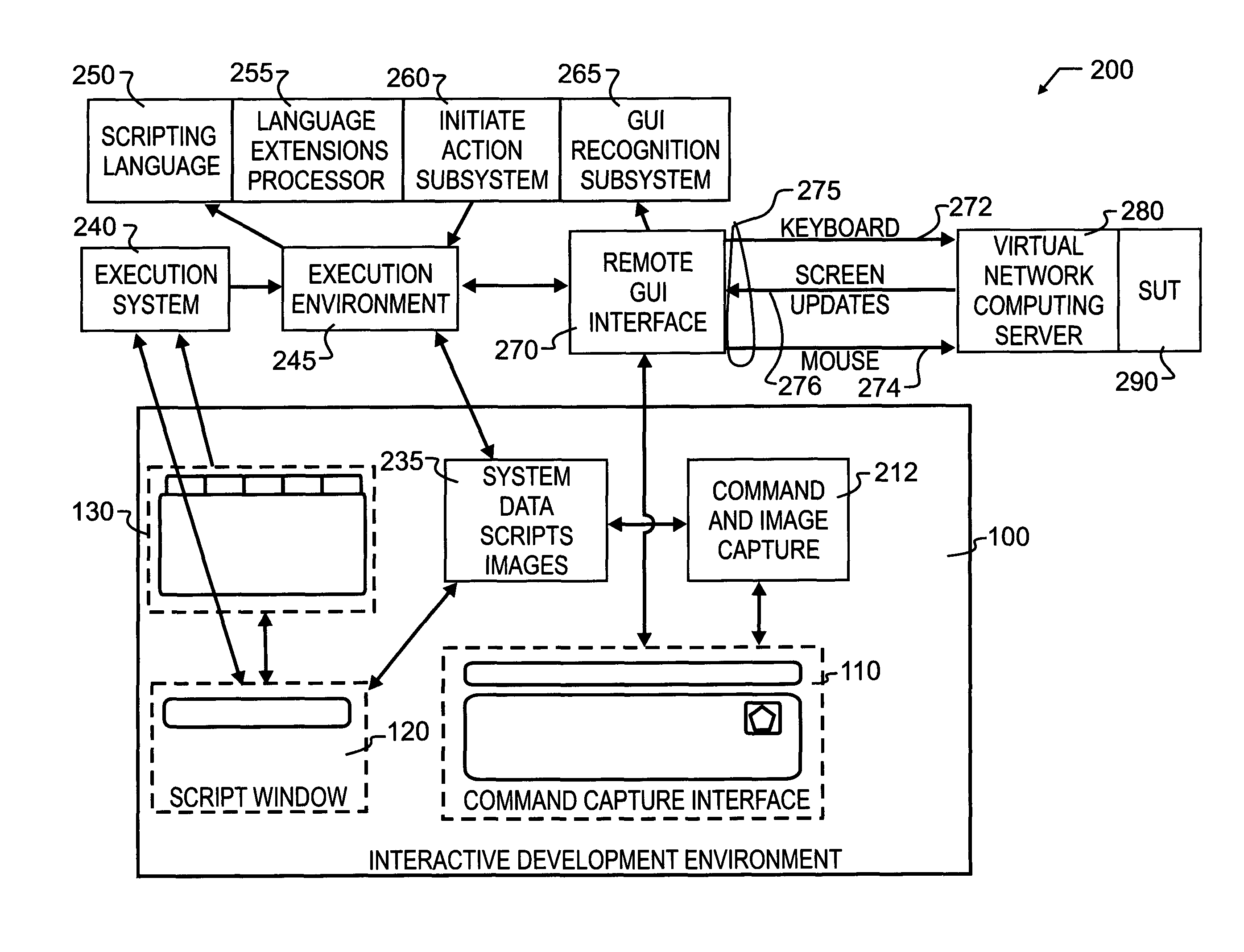
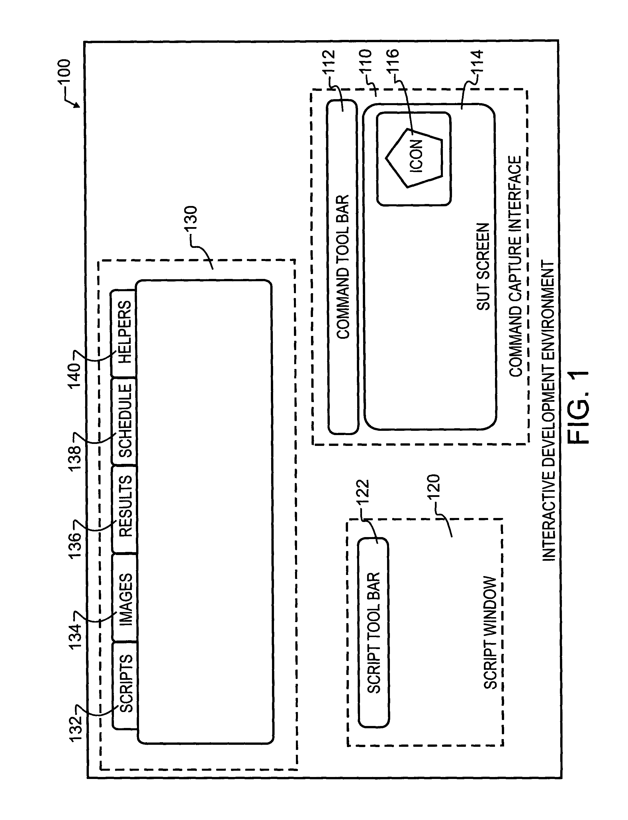
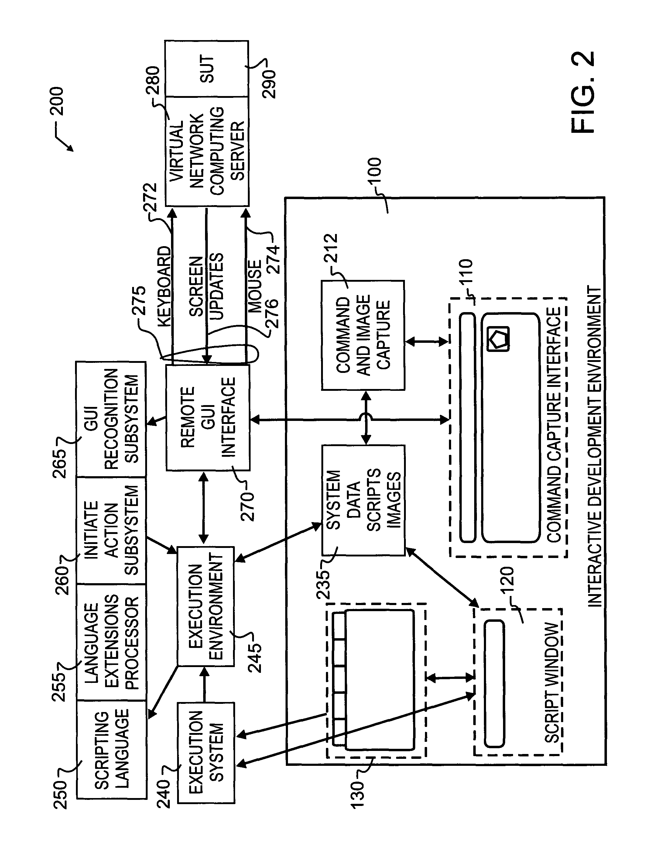
[0020]Manifested in the preferred embodiment, the present invention provides a computer user the ability to control any other computer connected through an interface, using the standard graphical user interface (GUI). As illustrated in FIG. 1, a user interface which takes the form of an interactive development environment (IDE) 100, will preferably include several functional windows 110, 120, 130 therein. More particularly, window 110 provides a command capture interface which most preferably provides a system-under-test (SUT) screen display 114 which provides a visual depiction of the display screen generated by the system for which the operation of the interactive development environment 100 is designed to control. Within that display there will be various graphical representations 116 that may take the form of icons as illustrated, or various buttons, message boxes, prompts or any other graphical image or control. The depiction may be an exact copy of the remote graphical user in...


PUM


Abstract

A high level interface between a remote computer and local computer operator permits the remote computer to be controlled via a sequence of interactions. The remote computer may be monitored for display information which is expected, and also controlled in the event the expected information either is or is not obtained. Command language extensions are provided which extend and complement a basic scripting language. Scripts with embedded command language extensions may be executed through a remote interface, permitting remote testing, operation and evaluation. The development of the scripts, including embedded command language extensions, may be prepared through execution of commands at the local computer on a depiction of the GUI received from the remote computer, and subsequently saved as a script.

Description

BACKGROUND OF THE INVENTION[0001]1. Field of the Invention[0002]This invention pertains generally to computer systems, and more particularly to methods and techniques for monitoring, testing and controlling the operation of one or more computers through communications links.[0003]2. Description of the Related Art[0004]With the early development of computers, all processing capability was located at a single computer system. These early machines were massive structures using many vacuum tubes, the result of which was the generation of an enormous amount of heat, and an associated sensitivity to environment. With these massive structures, all processing was performed centrally at this main computer, owing to the substantial expense required for isolation and environmental control. While remote communications with a computer system were sometimes used, the use was extremely infrequent and necessarily limited owing to the poor communications capability available at the time. These limit...

Claims


Application Information

Patent Timeline
Patent Type & Authority Patents(United States)
IPC IPC(8): G06F3/048
CPCG06F9/4445G06F11/2273G06F3/0487G06F3/04842G06F3/04817G06T7/246G06F9/452G06T7/0008G03G15/50G06F11/3672G06T7/001G06F11/3414G06F11/36G06F2201/875G06F3/1415G06T9/004G06F3/0481G06F11/3664G06F11/3688
Inventor MCINTOSH, JOHN W.SIMONS, DOUGLAS P.GILLASPIE, JONATHAN D.BIEBER, RAY L.
Owner EGGPLANT SOFTWARE INC
Why Eureka
Eureka Blog
Learn More