Inlet electromagnetic flow control

a technology of electromagnetic flow and inlet electromagnetic flow, which is applied in the direction of air-flow influencers, marine propulsion, and vessel construction, etc., can solve the problems of reducing the overall engine performance, poor performance and/or stalling of aircraft engines, and exacerbated problems

Active Publication Date: 2011-01-18
LOCKHEED MARTIN CORP
View PDF46 Cites 34 Cited by
  • Summary
  • Abstract
  • Description
  • Claims
  • Application Information

AI Technical Summary

Problems solved by technology

Flow field disturbances generated by fluid flow over aerodynamic surfaces within the inlet can buffet and fatigue downstream components exposed to these disturbances and reduce overall engine performance.
Disturbances can also be ingested within engine air intakes leading to poor performance and / or stalling of the aircraft engines.
This problem is exacerbated when the engine inlets have serpentine flow paths or exotic aperture shapes.
These inlets and outlets may cause excessive propulsion performance losses.
Stalling the aircraft engine creates a potentially hazardous condition.
Any of these changes may involve increased cost and weight associated with the aircraft.
However, these vanes result in increased weight and reduced performance over the engine's entire operating envelope.
These solutions have many inherent disadvantages which penalize aircraft performance.
Such inlets are typically made of large, heavy metal flaps which mechanically alter their geometry by diverting fluid flow with physical blockage, and thus have to endure the high pressures associated with fluid flow.
In these inlets, the actuators used to adjust the flaps to appropriate positions in the fluid flow tend to be heavy, expensive and complex because of the forces presented by the fluid flow which the flaps must overcome.
Variable geometry inlets are also difficult to implement on exotic nozzle aperture shapes.
Although the injection of a secondary flow will support a fixed geometry configuration, this method also introduces inefficiencies to the engine's operation.
Thus, injection can introduce inefficiency because the total momentum of the fluid flow is decreased by the decreased flow from the compressor section into the combustion section if compressed air is bled from the compressor section for injection.
This inefficiency can result in a reduced range of operations for a given fuel supply and a fuel flow.

Method used


Image

  • Inlet electromagnetic flow control
  • Inlet electromagnetic flow control
  • Inlet electromagnetic flow control

Examples


Embodiment Construction

[0022]Preferred embodiments of the present invention are illustrated in the figures like numerals being used to refer to like and corresponding parts of the various drawings.

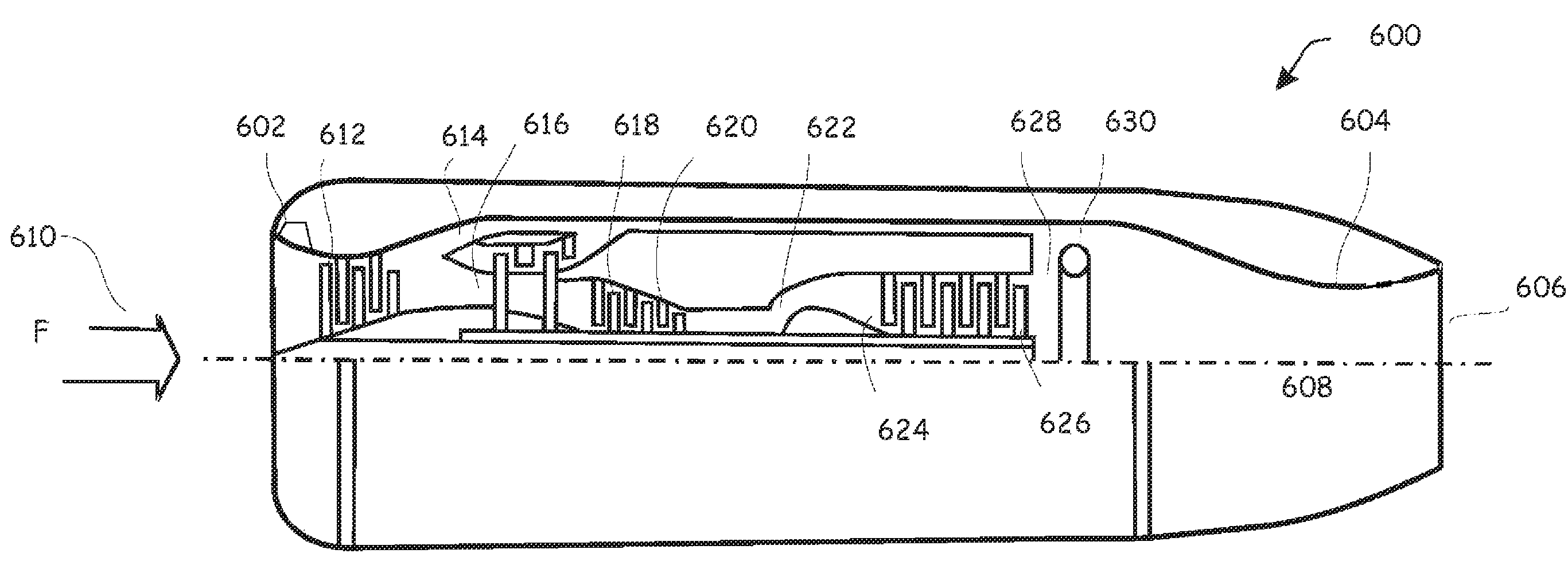
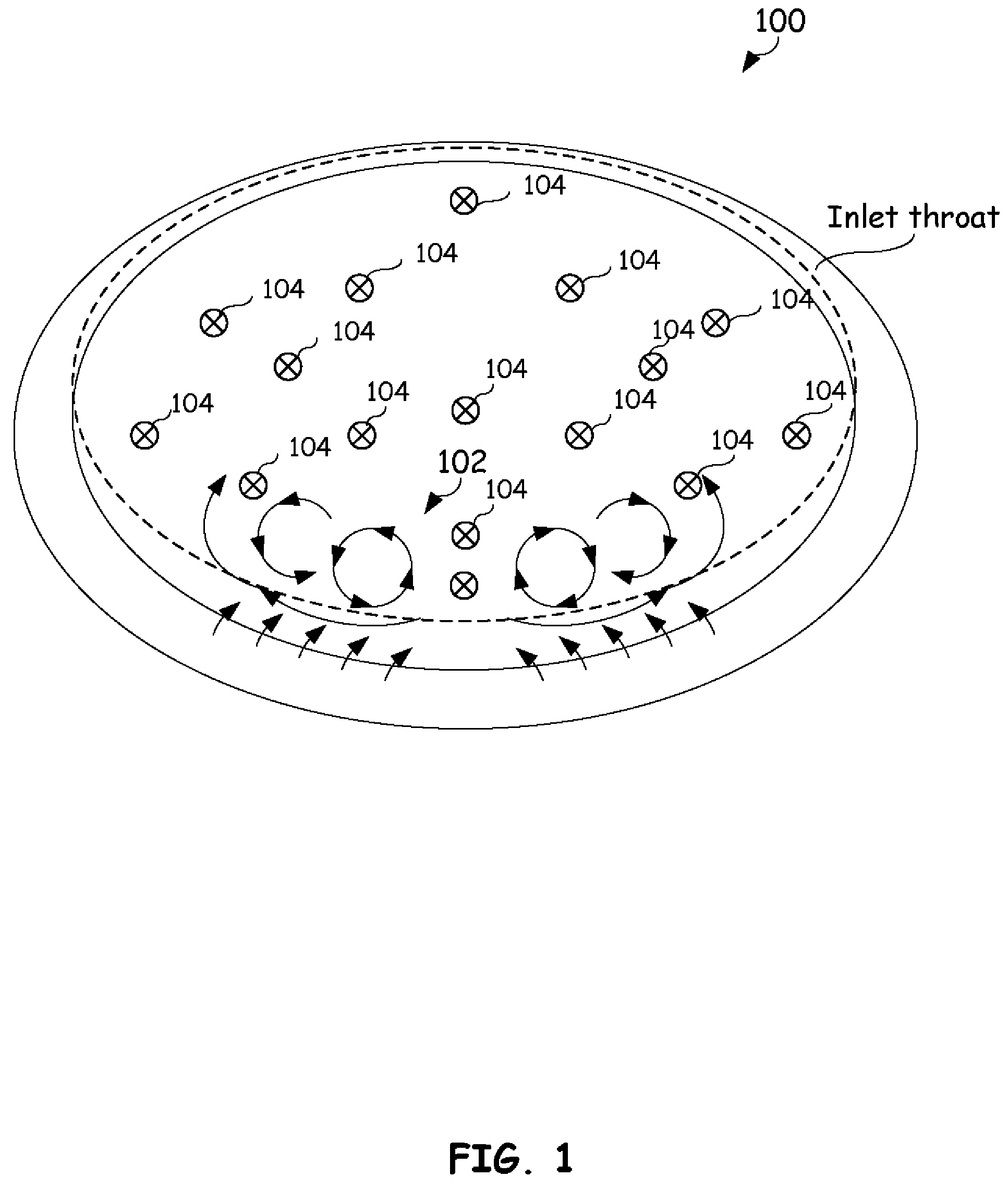
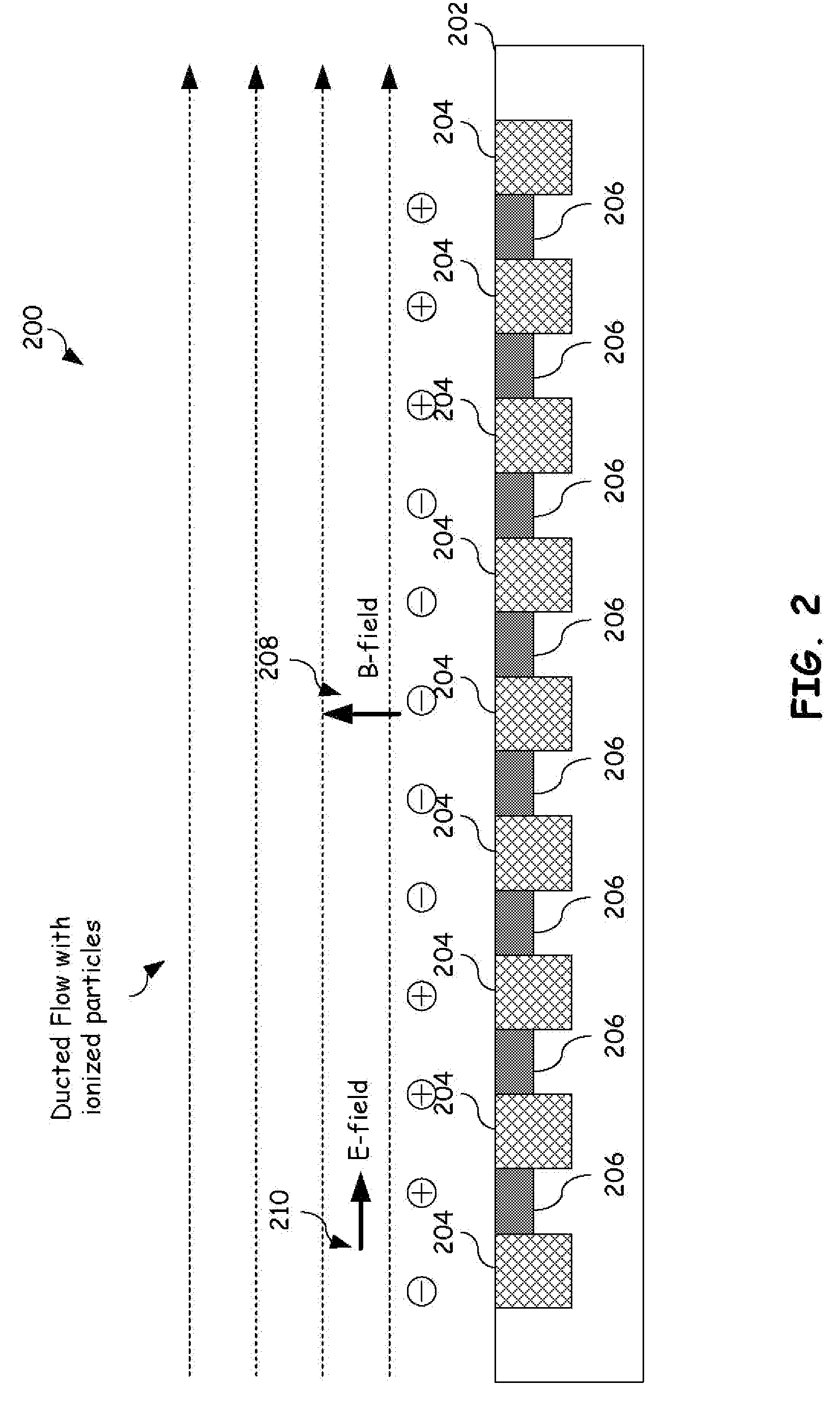
[0023]The present invention provides a system and method for manipulating fluid flow within an inlet that substantially eliminates or reduces disadvantages and problems associated with previously developed systems and methods. More specifically, the present invention provides a system and method to improve boundary layer profiles within a flow inlet and reduce buffeting or fatigue to engine components through the use of electromagnetic flow control. Embodiments place electromagnetic flow controllers (plasma accelerators) that accelerate low energy air within the lower regions of the boundary layer on ducted surfaces bounding the fluid flow. These electromagnetic flow controllers manipulate the flow behavior at this boundary of the fluid flow, to reduce flow separation within the primary fluid flow and improve in...


PUM


Abstract

A method to manipulate boundary layer conditions within a ducted fluid flow is provided. This method may be used to attach fluid flow to ducted surfaces bounding the fluid flow. This involves flowing a fluid over the surface wherein the fluid contains positively charged ions and electrons. An electric field accelerates ions and electrons in directions parallel to the electric field. The accelerated positively charged ions accelerate low energy air within lower regions of a boundary layer over the ducted surfaces bounding the ducted fluid flow. A magnetic field at the surface redirects ions and electrons based on their velocity and charge. The magnetic field imparts little force on the relatively heavy and slow moving positive ions but has a significant impact on the relatively fast moving, light weight electrons.

Description

TECHNICAL FIELD OF THE INVENTION[0001]The present invention relates generally to manipulation of fluid flow and more particularly, a system and method for manipulating a ducted ionized fluid flow.BACKGROUND OF THE INVENTION[0002]Most modern aircraft are powered by gas turbine engines, also known as jet engines. There are several types of jet engines, but all jet engines have certain parts in common. For example, all jet engines have an inlet with which to bring in free stream air into the engine. The inlet sits upstream of the compressor and, while the inlet does no work on the flow, there are important design features associated with the inlet. The total pressure through the inlet changes because of several flow effects. The inlet pressure performance is often characterized by the inlet pressure recovery, which measures the amount of free stream flow conditions that are recovered. This pressure recovery depends on a wide variety of factors, including inlet shape, aircraft speed, ai...

Claims


Application Information

Patent Timeline
Patent Type & Authority Patents(United States)
IPC IPC(8): B63H11/00B64D33/02
CPCB64C23/005B64D27/20B64D33/02F02C7/04F03H1/00H05H1/54B64D2033/0226F05D2270/172Y02T50/166Y02T50/44B64C2230/12Y02T50/10Y02T50/40Y10T137/206
Inventor HAGSETH, PAUL E.MCCLURE, PAUL D.
Owner LOCKHEED MARTIN CORP
Why Eureka
Try Eureka