Liquid ejecting apparatus and method of controlling liquid ejecting apparatus

a liquid ejecting apparatus and liquid ejecting technology, which is applied in the direction of printing, other printing apparatus, etc., can solve the problems of adversely affecting the subsequent discharge action of ink droplets, adversely affecting the discharge characteristics of ink droplets, and problematic residual vibration in ink present in the pressure chamber, so as to achieve stable discharging of liquid droplets and suppress residual vibration

Inactive Publication Date: 2011-01-18
SEIKO EPSON CORP
View PDF17 Cites 6 Cited by
  • Summary
  • Abstract
  • Description
  • Claims
  • Application Information

AI Technical Summary

Benefits of technology

[0008]An advantage of some aspects of the invention is that it provides a liquid ejecting apparatus that is capable of stably discharging liquid droplets by suppressing residual vibration that occurs after the liquid droplets are discharged and a method of controlling a liquid ejecting apparatus.

Problems solved by technology

However, after ink droplets are discharged, residual vibration in the ink present in the pressure chambers is problematic.
That is, the behavior of meniscus is disturbed by the residual vibration and, thereby, ink droplets may be undesirably discharged or may adversely affect subsequent discharge action of ink droplets.
The residual vibration of the piezoelectric vibrators may also adversely affect the discharge characteristics of ink droplets.

Method used


Image

  • Liquid ejecting apparatus and method of controlling liquid ejecting apparatus
  • Liquid ejecting apparatus and method of controlling liquid ejecting apparatus
  • Liquid ejecting apparatus and method of controlling liquid ejecting apparatus

Examples


Embodiment Construction

[0030]An embodiment of the invention will now be described with reference to the accompanying drawings. Note that, in the following, an ink jet printer (hereinafter, simply referred to as a printer) shown in FIG. 1 is an example of a liquid ejecting apparatus according to the invention.

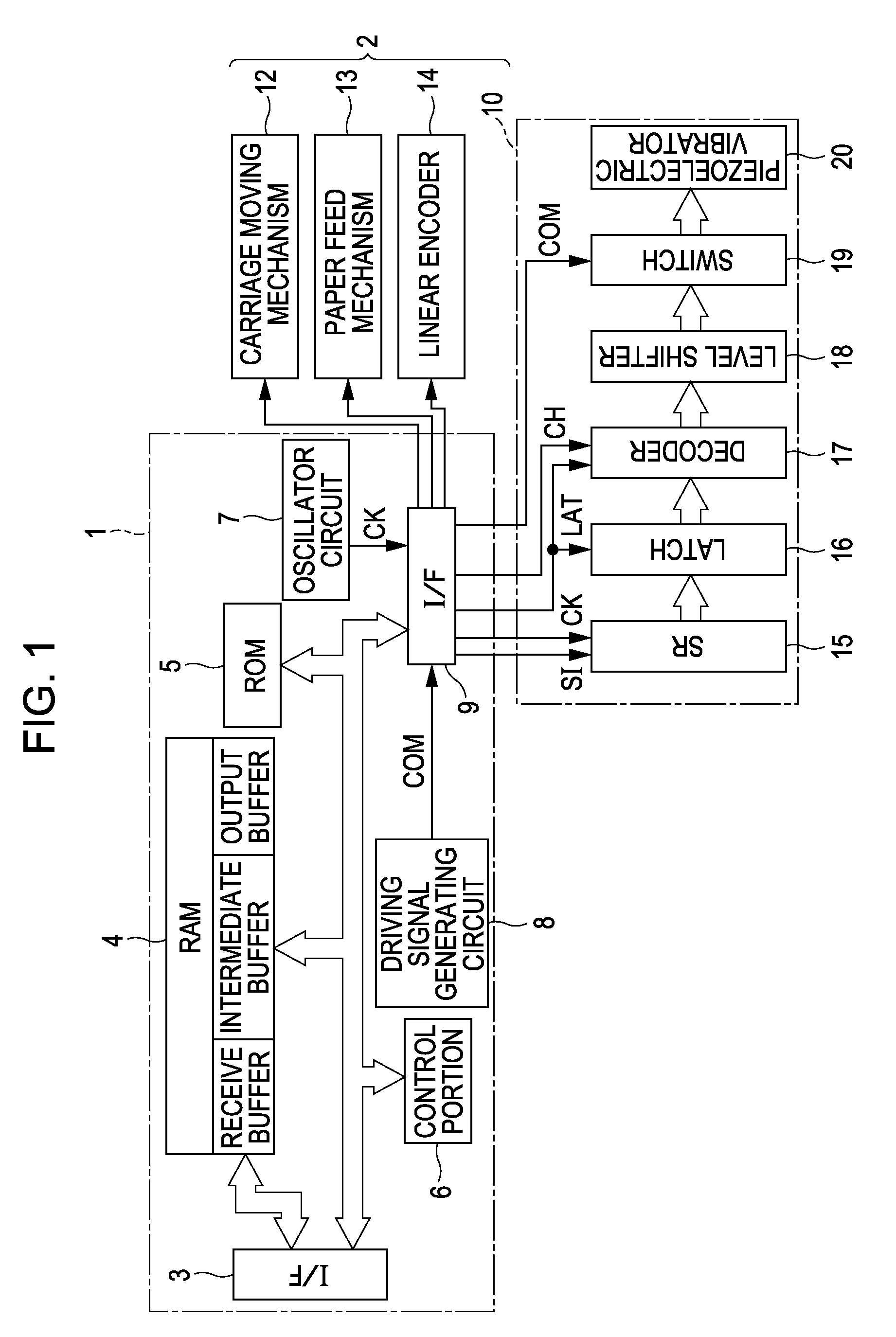
[0031]FIG. 1 is a block diagram illustrating an electrical configuration of the printer. The printer schematically includes a printer controller 1 and a print engine 2. The printer controller 1 includes an external interface (external I / F) 3, a RAM 4, a ROM 5, a control portion 6, an oscillator circuit 7, a driving signal generating circuit 8 (which is an example of a driving signal generating device in the aspect of the invention) and an internal interface (internal I / F) 9. The external I / F 3 gives and receives data with an external device such as a host computer. The RAM 4 stores various data, or the like. The ROM 5 stores control routines, or the like, for various data processing. The control porti...


PUM


Abstract

A liquid ejecting apparatus includes a liquid ejecting head and a driving signal generating device. The liquid ejecting head includes a pressure generating device and a pressure chamber in communication with a nozzle opening. The pressure generating device generates pressure fluctuation in liquid in the pressure chamber. The liquid ejecting head discharges the liquid from the nozzle opening in the form of a liquid droplet. The driving signal generating device generates a driving signal that includes a discharge pulse for discharging the liquid droplet during every discharge period. The driving signal generating device sets, into the discharge pulse, an expansion element for expanding the pressure chamber, a discharge element for discharging the liquid droplet by contracting the pressure chamber, and a vibration damping element for suppressing residual vibration, which occurs in the pressure chamber after the liquid droplet is discharged, by further contracting the pressure chamber.

Description

BACKGROUND[0001]1. Technical Field[0002]The present invention relates to a liquid ejecting apparatus, such as an ink jet printer, and a method of controlling a liquid ejecting apparatus and, more particularly, to a liquid ejecting apparatus provided with a liquid ejecting head that discharges a liquid droplet from a nozzle opening by means of a pressure generating unit being actuated through a supply of driving signal and a method of controlling the same.[0003]2. Related Art[0004]A liquid ejecting apparatus is provided with a liquid ejecting head that is capable of discharging liquid in the form of liquid droplets. The liquid ejecting apparatus is an apparatus that discharges various types of liquid from the liquid ejecting head. A typical example of the liquid ejecting apparatus may be, for example, an image recording apparatus, such as an ink jet printer (hereinafter, simply referred to as a printer), that discharges liquid ink in the form of ink droplets to be directed onto a rec...

Claims


Application Information

Patent Timeline
Patent Type & Authority Patents(United States)
IPC IPC(8): B41J29/38
CPCB41J2/04581B41J2/04588
Inventor TERAMAE, HIROFUMI
Owner SEIKO EPSON CORP
Why Eureka
Try Eureka