Method and apparatus for monitoring particles in a gas turbine working fluid

a gas turbine and working fluid technology, applied in the direction of fluid pressure measurement by mechanical elements, volume flow measuring devices, amplifier modifications to reduce noise influence, etc., can solve the problems of solid particle matter entrapment, detriment to structural integrity,

Inactive Publication Date: 2011-01-18
SIEMENS ENERGY INC
View PDF22 Cites 13 Cited by
  • Summary
  • Abstract
  • Description
  • Claims
  • Application Information

AI Technical Summary

Problems solved by technology

Cooling allows the use of high engine operating temperatures that would otherwise be detrimental to the structural integrity of the blades and vanes.
An unintended consequence of this removal and return of cooling air from the turbine system is that solid particle matter is entrained in the cooling air stream.

Method used


Image

  • Method and apparatus for monitoring particles in a gas turbine working fluid
  • Method and apparatus for monitoring particles in a gas turbine working fluid
  • Method and apparatus for monitoring particles in a gas turbine working fluid

Examples


Embodiment Construction

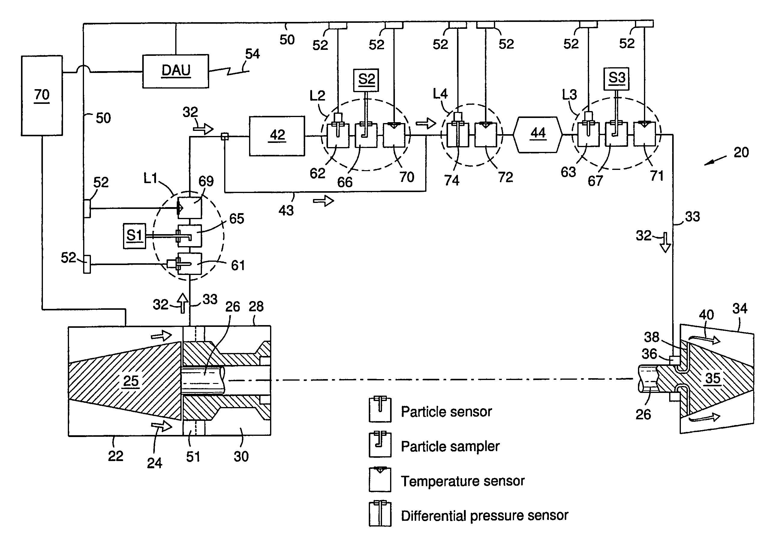
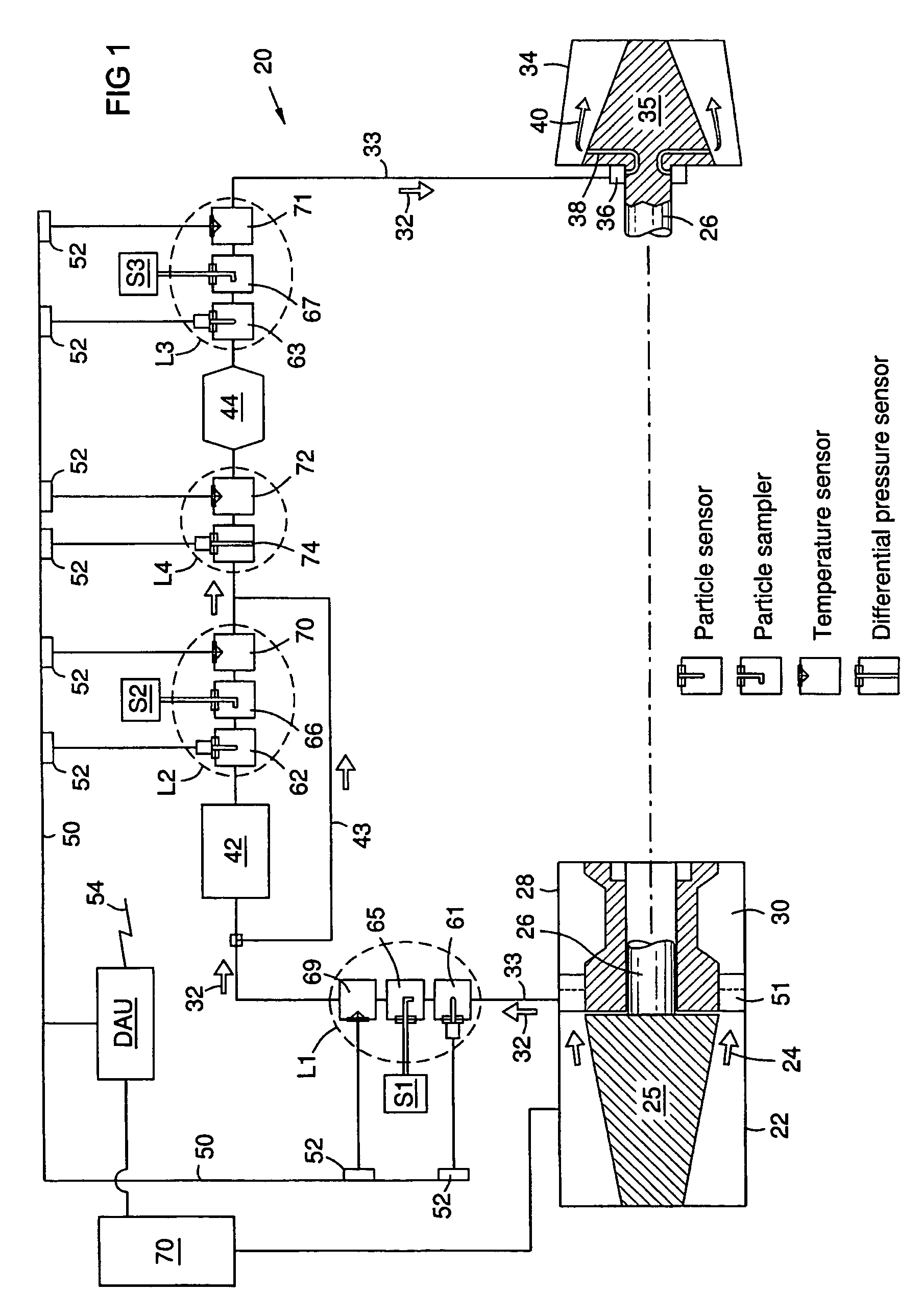
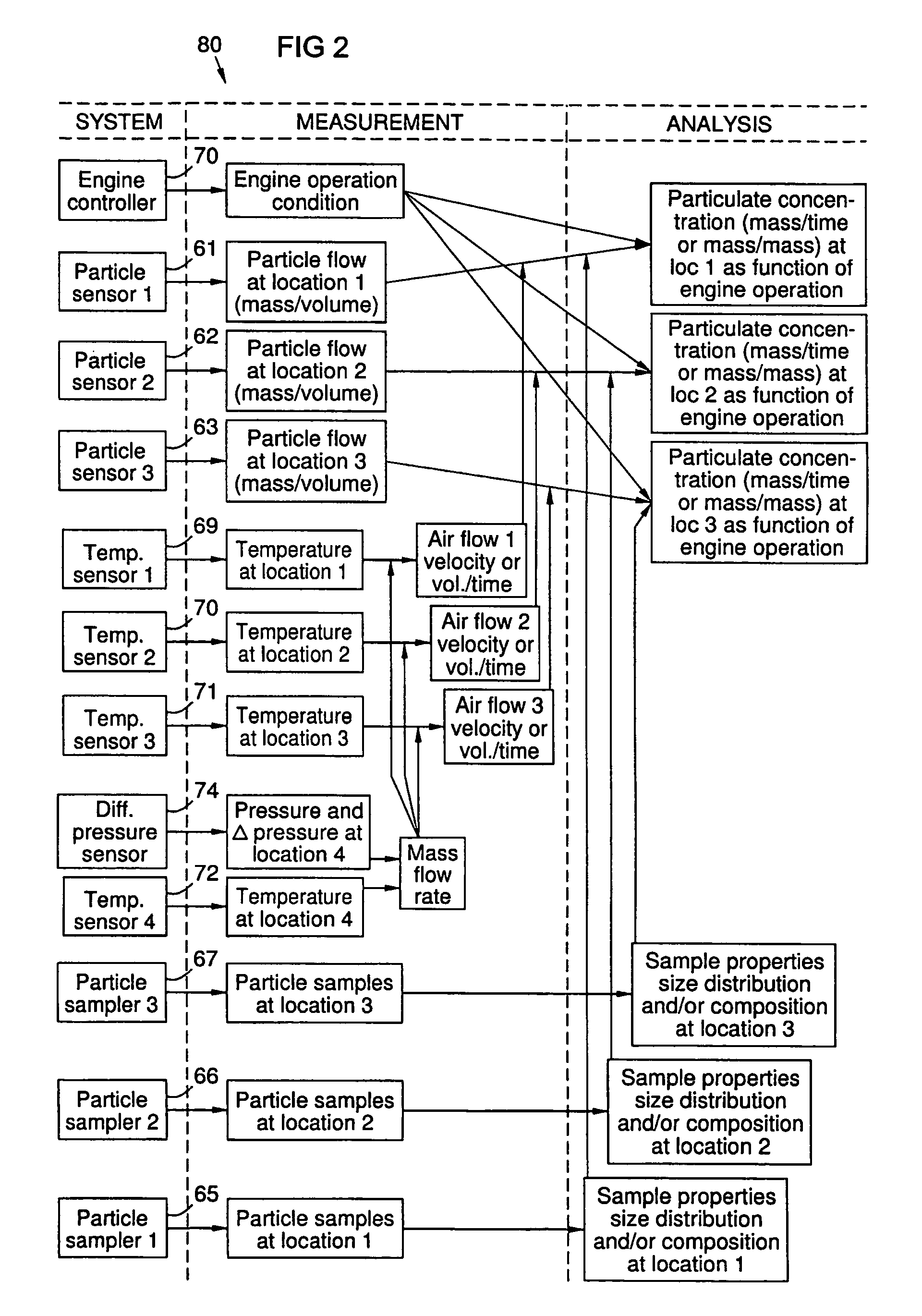
[0007]Contaminant particles entrained in the cooling air of a gas turbine engine can accumulate on surfaces in the cooling air piping and channels. The inventors have recognized that such accumulations can increase maintenance costs and reduce the availability of the engine. The inventors further recognized that the cooling air is representative of the gas turbine working fluid flow at the point of cooling air extraction, and that it contains particles ingested from the environment and those entrained from internal corrosion in the compressor and the cooling system. Predicting particle accumulations using analytical methods alone has been unsatisfactory, because particle concentrations depend upon a variety of unpredictable factors such as changes in environmental conditions. Such factors can cause unexpected acceleration of corrosion or ingestion of particles. The inventors recognized that continuously monitoring particles in the cooling air could offer significant improvements in ...


PUM


Abstract

A method and system for monitoring a gas turbine engine (20) to predict maintenance requirements. Particles suspended in a gas flow (24, 32) of the engine (20) are monitored and quantified to predict a particle accumulation rate. Monitoring may be done using particle flow sensors (61-63) in a diverted portion (33) of the working gas flow (24), such as in the cooling gas flow (32). Particle sampling (S1-S3) may be done to determine particle size and composition distributions. Particle mass flow rates may then be continuously monitored per engine operating condition, and compared to predetermined values such as a normal upper limit per engine operating condition. An integrated particle mass flow may be used in conjunction with an instantaneous mass flow rate to predict a maintenance requirement. Multiple locations (L1-L3) may be monitored to recognize a maintenance requirement by flow section or component.

Description

FIELD OF THE INVENTION[0001]The invention relates to continuous monitoring of contaminant particles suspended in a gas flow in a gas turbine engine to recognize and predict maintenance requirements for components of the gas turbine and cooling system.BACKGROUND OF THE INVENTION[0002]Gas turbine engines use an air compressor to provide a working fluid flow for combustion and power cycles. A portion of this working flow may be diverted into a cooling system to provide cooling air for turbine blades and vanes. Cooling air may be routed through a heat exchanger, then channeled through the interior of each blade and vane airfoil, and finally discharged from small holes in these airfoils into the turbine air stream to draw heat away from the surfaces of the airfoils. Cooling allows the use of high engine operating temperatures that would otherwise be detrimental to the structural integrity of the blades and vanes.[0003]An unintended consequence of this removal and return of cooling air fr...

Claims


Application Information

Patent Timeline
Patent Type & Authority Patents(United States)
IPC IPC(8): F01D21/00F01D21/14F01D21/10F01D21/12G01M99/00
CPCF01D21/003G01N1/2202G01N15/02F05D2260/607F05D2260/80
Inventor BUNCE, RICHARD H.DOVALI-SOLIS, FRANCISCO
Owner SIEMENS ENERGY INC
Why Eureka
Try Eureka