Filter assemblies, filter cartridges and methods for removing filter cartridges from filter assemblies

a technology of filter assembly and filter cartridge, which is applied in the direction of moving filtering element filters, filtration separation, and separation processes, etc., can solve the problems of flexing and stretching, more difficult to slide the filter cartridge out of the filter housing, and more difficult to remove the filter cartridge, so as to achieve enhanced frictional engagement and more filter cartridge removal

Active Publication Date: 2011-01-18
PALL CORP
View PDF30 Cites 11 Cited by
  • Summary
  • Abstract
  • Description
  • Claims
  • Application Information

AI Technical Summary

Benefits of technology

[0004]A filter cartridge may include a filter pack through which the fluid is directed to separate the undesirable substances from the fluid. The filter pack, which may be a pleated structure formed from one or more polymeric materials, preferably has a hollow, cylindrical configuration. Fluid is directed through the hollow, cylindrical filter pack in a generally radial direction either inside out or outside in. To support the filter pack against the force of the fluid flowing through the filter pack, a cylindrical support having openings is positioned closely adjacent to the filter pack. For example, the cylindrical support may be a perforated cage positioned closely adjacent to the exterior of the filter pack. The perforated cage then supports the filter pack against the radially outwardly directed force of fluid flowing inside out through the filter pack and through the perforations in the perforated cage. Alternatively, the cylindrical support may be a perforated core positioned closely adjacent to the interior of the filter pack. The perforated core then supports the filter pack against the radially inwardly directed force of fluid flowing outside in through the filter pack and through the perforations in the core. Occasionally, it is desirable to have both a perforated cage and a perforated core supporting the filter pack. To minimize the amount of waste that is generated in replacing a clogged filter cartridge, the cylindrical support, e.g., the perforated cage or core, may be fashioned as a permanent part of the reusable filter housing rather than a part of the disposable filter cartridge.
[0010]Filter assemblies, filter cartridges and removal methods embodying the invention offer many advantages. For example, the replaceable filter cartridge may become lodged within the filter housing with the filter pack pressed into the openings in the reusable cylindrical support and / or an O-ring tightly engaged with the filter housing, locking the two together. However, removal of the filter cartridge from the cylindrical support and the filter housing is nonetheless fast and effective. Removing the removable portion of the filter housing engages the link elements of the linkage and transmits a twisting force and / or an axial force to the filter cartridge. This twisting and / or axial force breaks the filter cartridge free from the filter housing, including the stationary cylindrical support. In many embodiments, the removable portion of the filter housing, e.g., a cover assembly or a header assembly, may be threaded to the remainder of the filter housing, and the removable portion of the filter housing can be unscrewed by a lever, such as a screwdriver or a wrench. This greatly enhances the mechanical advantage available to break the filter cartridge free of the filter housing and the stationary support. Further, the link elements can be configured to transmit both an axial force and a twisting force. Unscrewing the threaded rotatable portion then not only twists the filter cartridge about the stationary support but also pulls the filter cartridge axially along the stationary support.

Problems solved by technology

For a variety of reasons, a filter cartridge can become lodged within the filter housing, which may make removal of the filter cartridge more difficult.
This enhanced frictional engagement between the seal and the filter housing can then make it more difficult to slide the filter cartridge out of the filter housing.
This is a particular problem for filter packs formed substantially from polymeric materials, which can flex and stretch, especially if the fluid flowing through the filter pack is warm.
With portions of the filter pack locked into the openings of the cylindrical support, the replaceable filter cartridge can be more difficult to remove from the permanent cylindrical support.

Method used


Image

  • Filter assemblies, filter cartridges and methods for removing filter cartridges from filter assemblies
  • Filter assemblies, filter cartridges and methods for removing filter cartridges from filter assemblies
  • Filter assemblies, filter cartridges and methods for removing filter cartridges from filter assemblies

Examples


Embodiment Construction

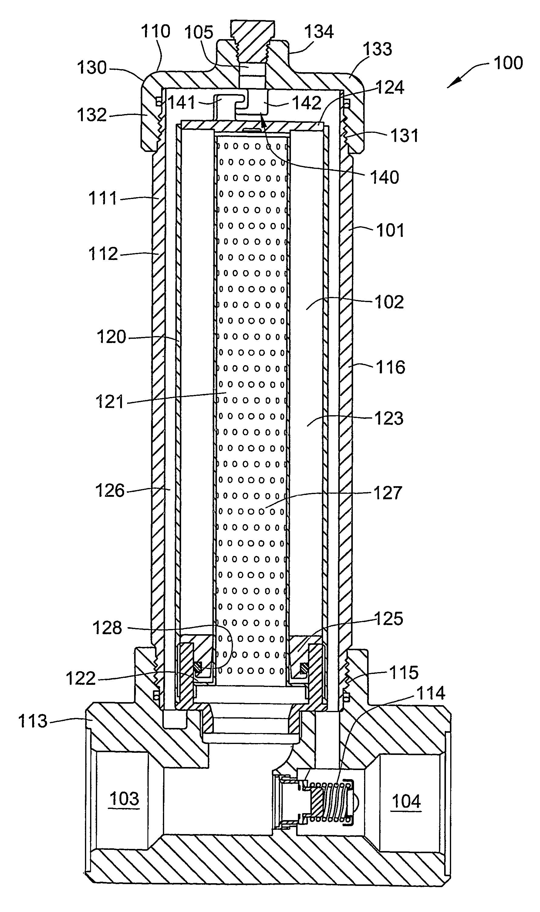
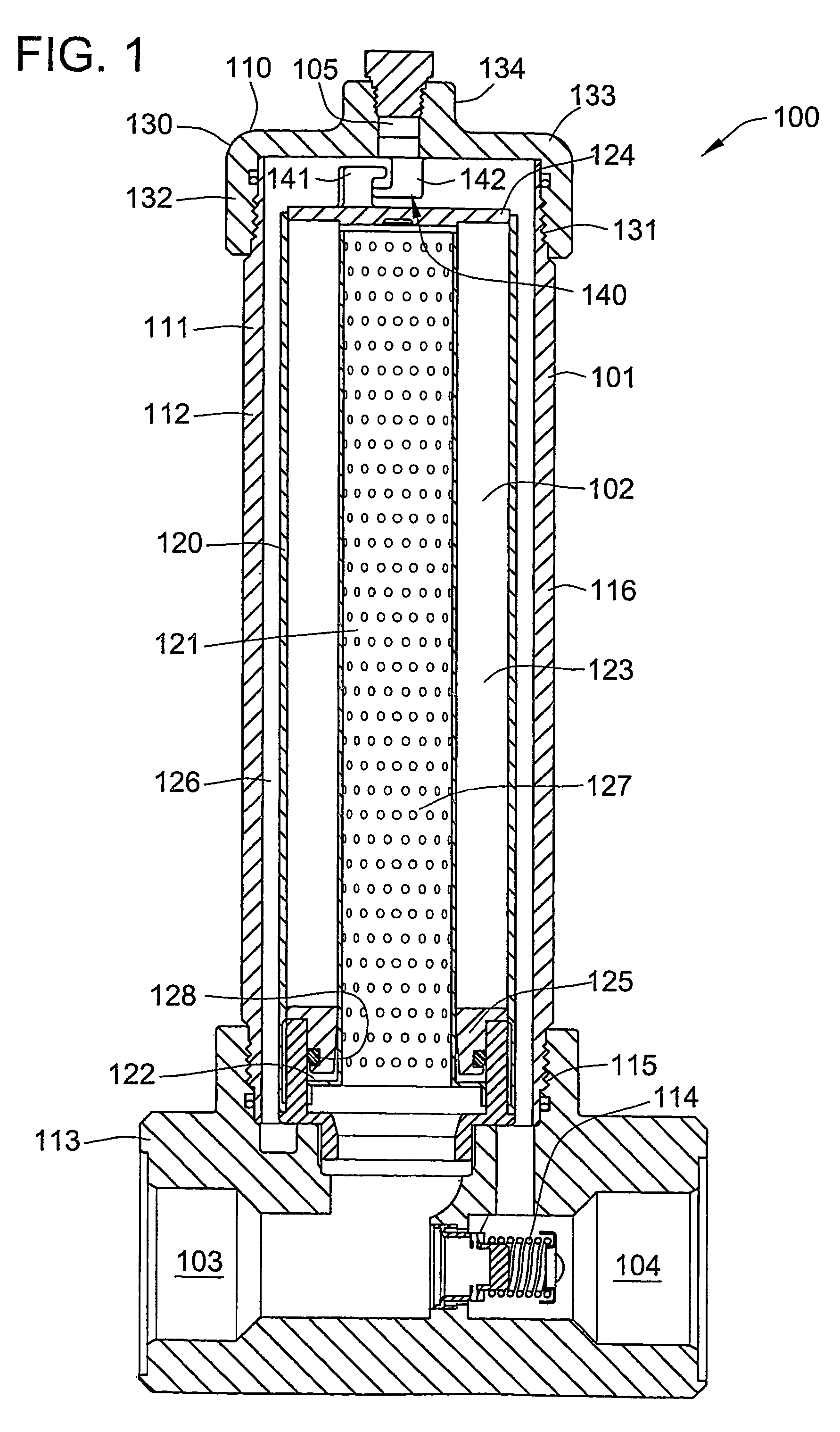
[0017]Filter assemblies embodying the invention may be configured in numerous ways. One example of a filter assembly 100 is shown in FIG. 1. The filter assembly 100 generally comprises a filter housing 101 and a filter cartridge 102. The filter housing 101 may include a fluid inlet 103 and a fluid outlet 104 and define a fluid flow path between the fluid inlet 103 and the fluid outlet 104. The filter cartridge 102 may be sealed in the filter housing 101 across the fluid flow path. The illustrated embodiment of the filter assembly 100 is thus arranged for dead-end filtration, and the fluid outlet 104 is a filtrate outlet. In other embodiments, the filter assembly may, for example, be arranged for cross-flow filtration, and the filter housing may include a fluid inlet and two fluid outlets, i.e., a filtrate or permeate outlet and a retentate or concentrate outlet. The filter housing 101 may include one or more additional ports, e.g., a vent or drain port 105.

[0018]The filter housing m...


PUM

PropertyMeasurementUnit
twisting forceaaaaaaaaaa
axial forceaaaaaaaaaa
forceaaaaaaaaaa

Abstract

A filter assembly (100) may comprise a filter cartridge (102) and a filter housing (101) which may include a cylindrical support (121) and a removable portion (110).

Description

[0001]This application is the United States national phase of International Application No. PCT / US2004 / 011117 which was filed on Apr. 12, 2004, and which claims the benefits of priority of U.S. Provisional Application No. 60 / 461,428, which was filed on Apr. 10, 2003, both of which are incorporated herein by reference.FIELD OF THE INVENTION[0002]The invention relates to filter assemblies and filter cartridges for separating undesirable substances from fluids, including liquids and gases. Undesirable substances which may be separated from a liquid include particulate matter, such as solid or gelatinous particles, as well as one or more liquid components from a mixture of liquids. Undesirable substances which may be separated from a gas include particulate matter, such as solid, gelatinous or liquid particles. Filter assemblies and filter cartridges embodying the invention may be used in any of these applications.[0003]The invention also relates to methods for removing filter cartridge...

Claims


Application Information

Patent Timeline
Patent Type & Authority Patents(United States)
IPC IPC(8): B01D29/15B01D35/34B01D35/30B01D29/23B01D29/21
CPCB01D29/21B01D29/96B01D2201/0407B01D2201/291B01D2201/301B01D2201/4015
Inventor BRANDT, JAY D.CHILDS, DAVID M.
Owner PALL CORP
Why Eureka
Try Eureka