

Method for purification of carbon dioxide using liquid carbon dioxide
a carbon dioxide and liquid carbon dioxide technology, applied in gas treatment, lighting and heating apparatus, inorganic chemistry, etc., can solve the problems of large amount of clean water used, waste, and ineffective removal from the stream by water scrubbers, so as to improve the absorption process, increase the yield of carbon dioxide, and high carbon dioxide yield
- Summary
- Abstract
- Description
- Claims
- Application Information
AI Technical Summary
Benefits of technology
Problems solved by technology
Method used
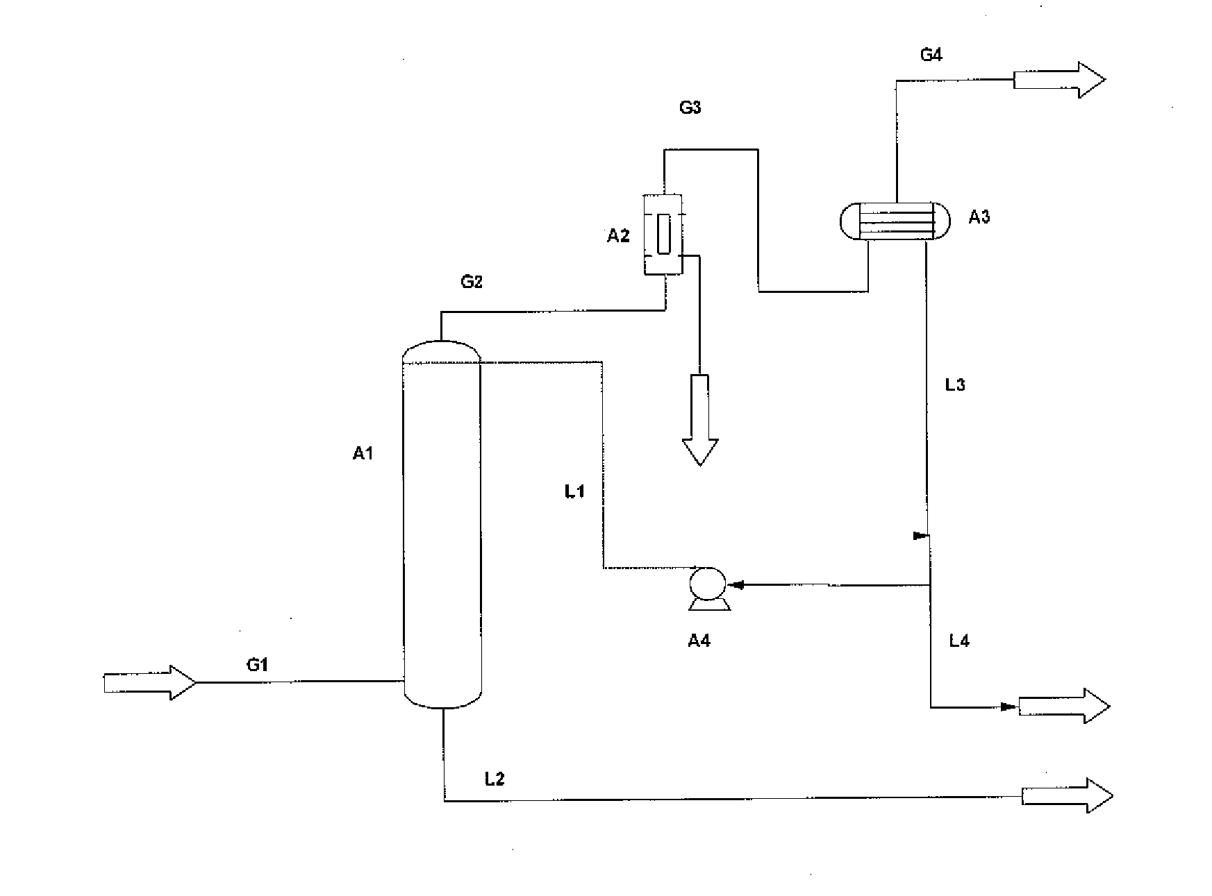
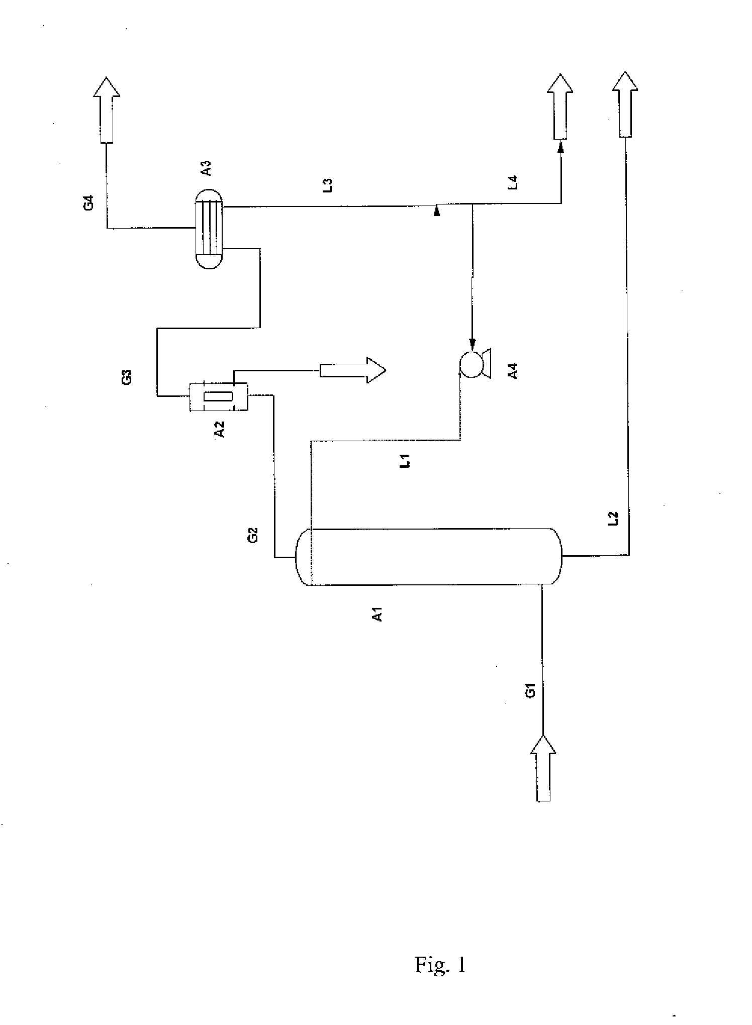
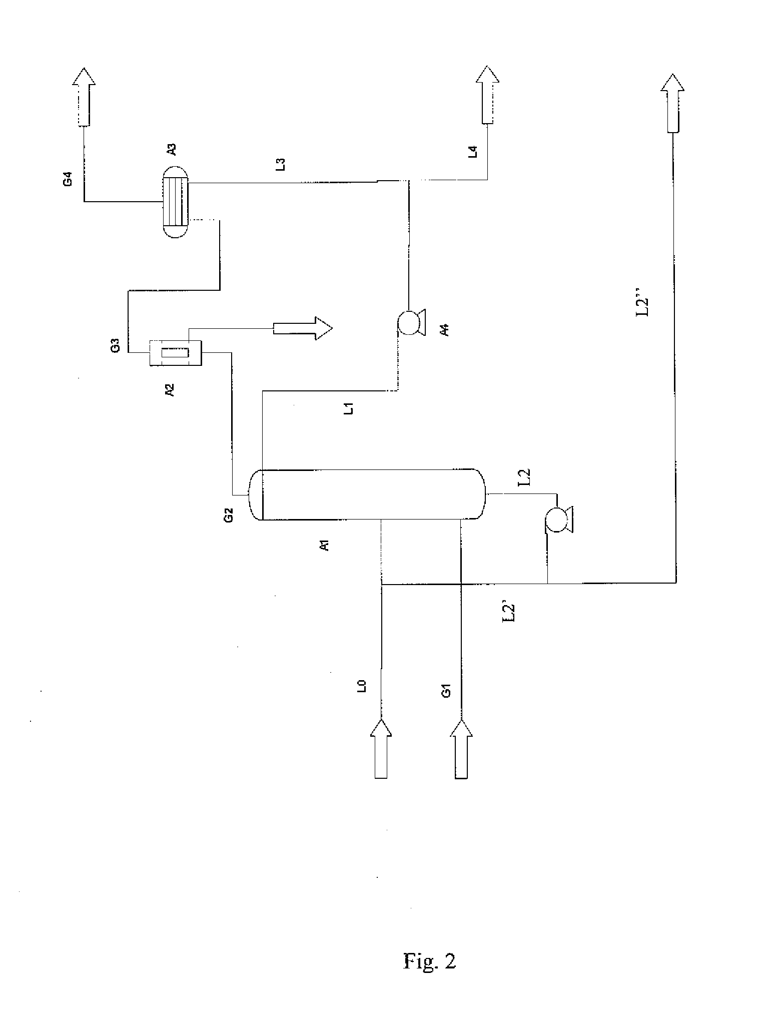
Image

Examples
Embodiment Construction
[0054]According to the present invention, a substantially pure CO2 stream comprises more than 80 weight-% CO2.
[0055]Throughout the description, unless otherwise indicated, all contents are given as weight-%.
[0056]Throughout the description and the claims the terms impurity and contaminant may be used interchangeably having the same meaning in the context of the present invention and both cover undesired substances in a carbon dioxide stream that should be removed.
[0057]Throughout the description and the claims the terms water activity reducing agent, agent and water inhibitor may be used interchangeably having the same meaning in the context of the present invention, and all cover a substance that is capable of removing water from a carbon dioxide stream.
[0058]Throughout the description and the claims the term water free or dry gaseous stream is a gaseous stream in which the water content is so low so as not to cause process related problems, such as freezing within pipes, container...
PUM
| Property | Measurement | Unit |
|---|---|---|
| pressure | aaaaa | aaaaa |
| pressure | aaaaa | aaaaa |
| temperatures | aaaaa | aaaaa |
Abstract
Description
Claims
Application Information