

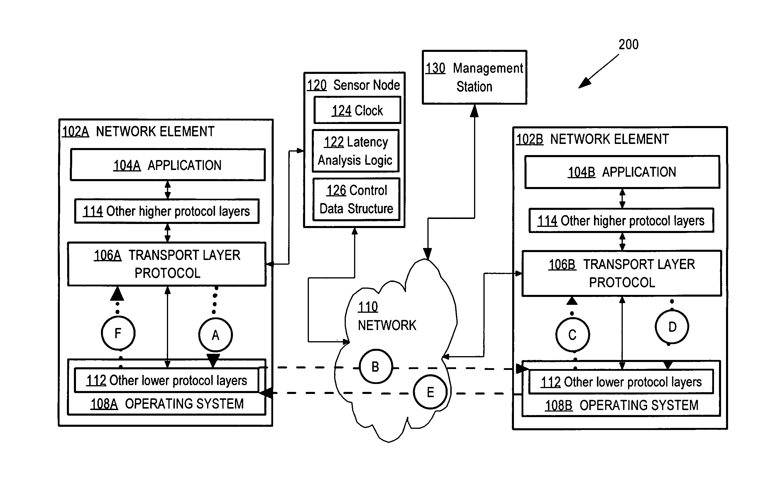
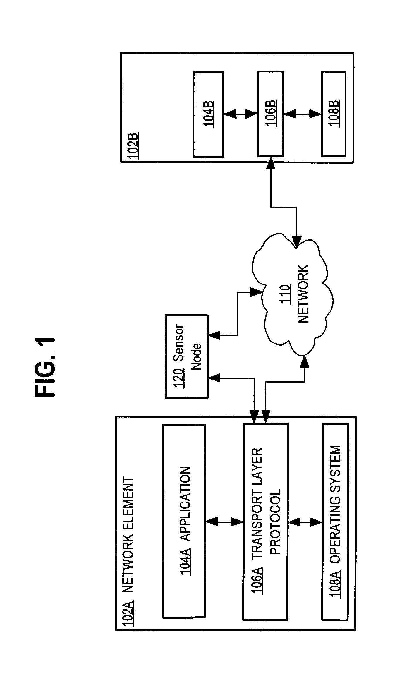
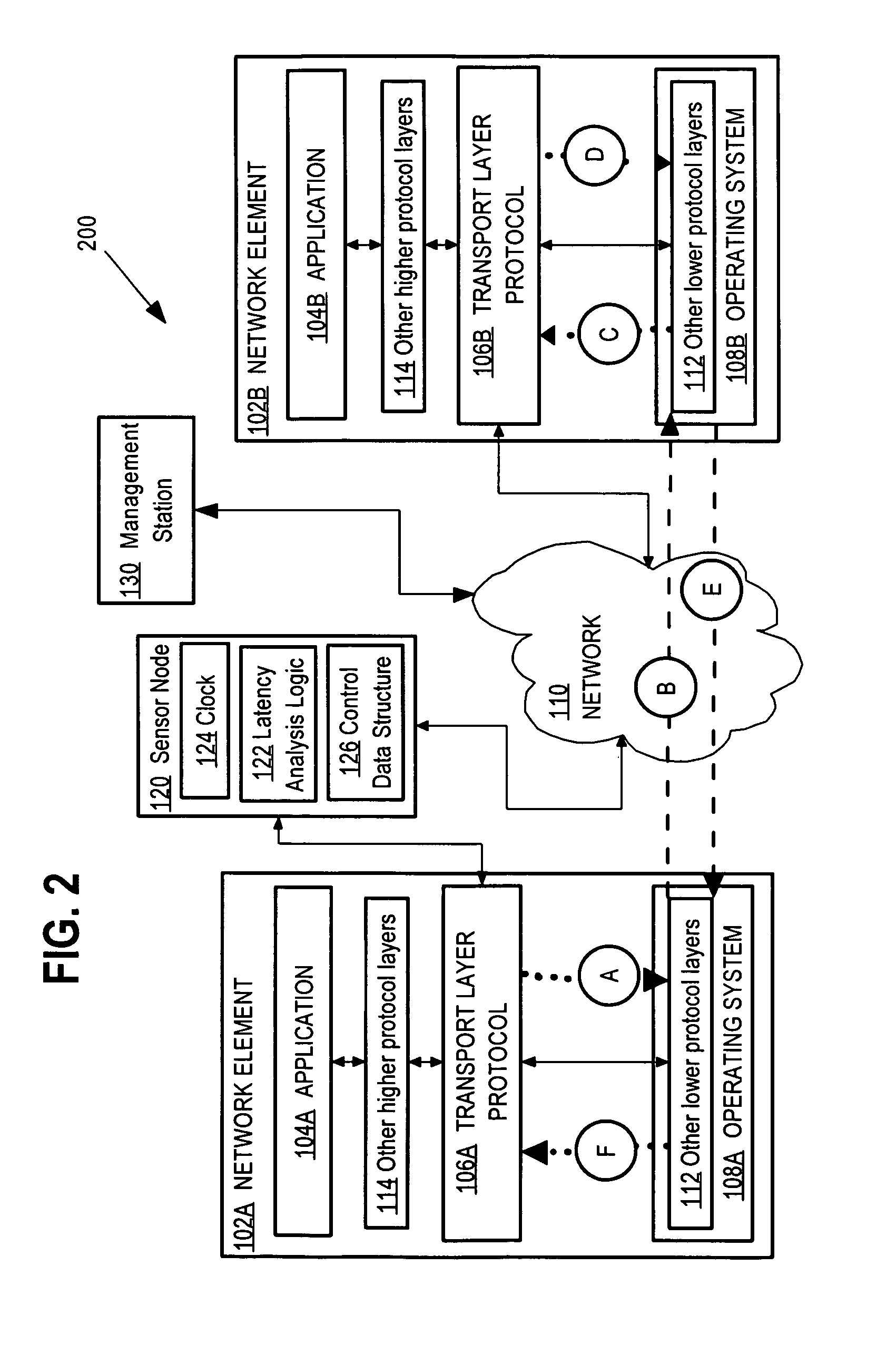
Network device that determines application-level network latency by monitoring option values in a transport layer message
a network device and transport layer technology, applied in the field of network data communication, can solve the problems of inaccurate tcp timestamp option, low reliability of tcp timestamp option, and inability to widely deploy,
- Summary
- Abstract
- Description
- Claims
- Application Information
AI Technical Summary
Problems solved by technology
Method used
Image

Examples
Embodiment Construction
A method and apparatus for determining application-level network latency by monitoring option values in a transport layer message are described. In the following description, for the purposes of explanation, numerous specific details are set forth in order to provide a thorough understanding of the present invention. It will be apparent, however, to one skilled in the art that the present invention may be practiced without these specific details. In other instances, well-known structures and devices are shown in block diagram form in order to avoid unnecessarily obscuring the present invention.
Embodiments are described herein according to the following outline:1.0 General Overview2.0 Structural and Functional Overview3.0 Determining Application-Level Network Latency by Monitoring Option Values in a Transport Layer Message4.0 Implementation Mechanisms—Hardware Overview5.0 Extensions and Alternatives
1.0 General Overview
The needs identified in the foregoing Background, and other needs ...
PUM
 Abstract
Description
Claims
Application Information