Flexibly integrating endpoint logic into varied platforms

a technology of endpoint logic and varied platforms, applied in the field of flexible integration of endpoint logic into varied platforms, can solve the problem of slow development of designs that accumulate these features

Inactive Publication Date: 2011-01-18
INTEL CORP
View PDF15 Cites 43 Cited by
  • Summary
  • Abstract
  • Description
  • Claims
  • Application Information

AI Technical Summary

Problems solved by technology

However, designs that accumulate these features are slow to emerge due to the difficulty of integra

Method used


Image

  • Flexibly integrating endpoint logic into varied platforms
  • Flexibly integrating endpoint logic into varied platforms
  • Flexibly integrating endpoint logic into varied platforms

Examples


Embodiment Construction

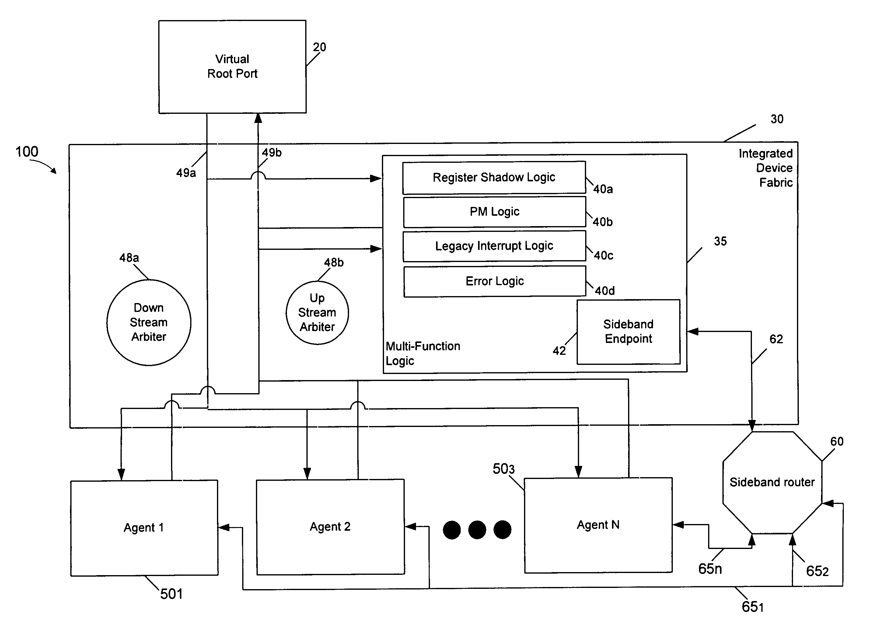
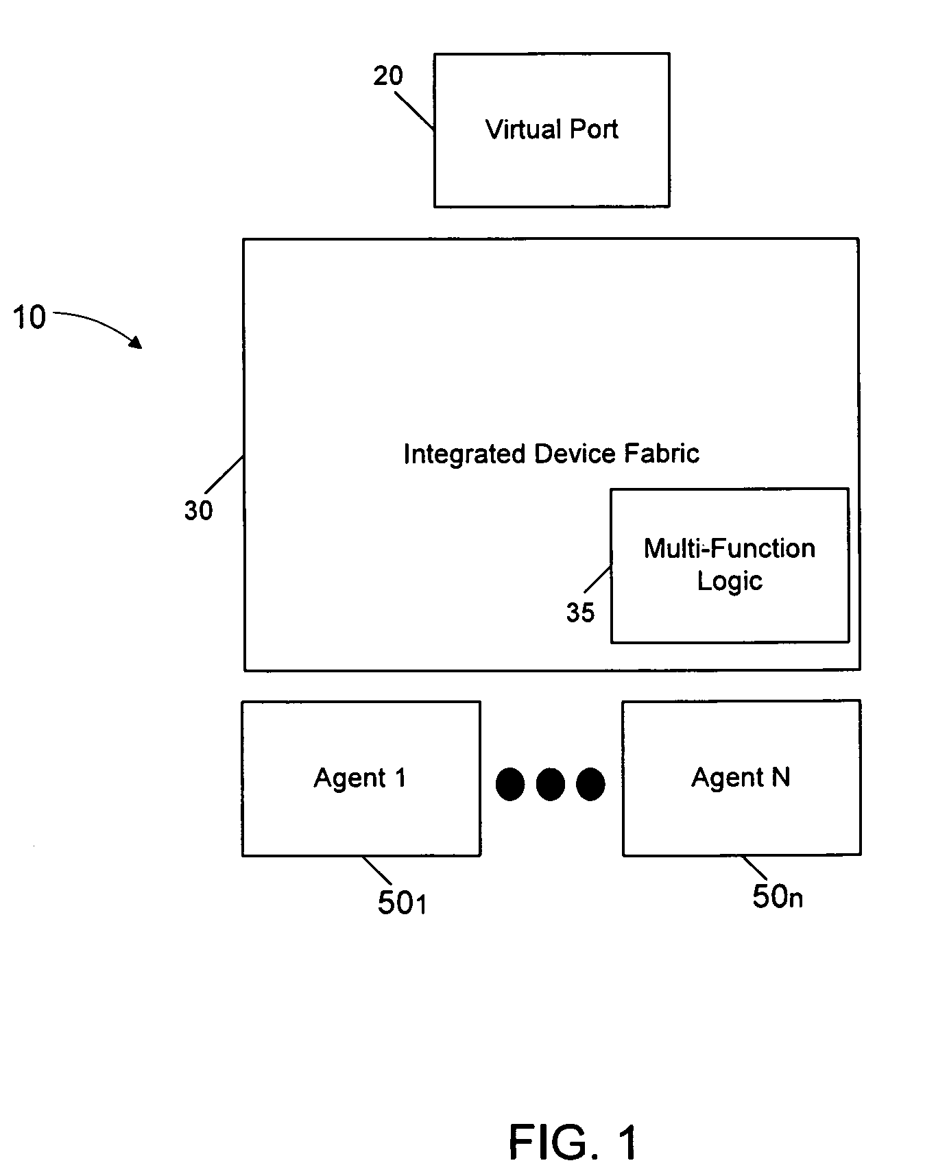
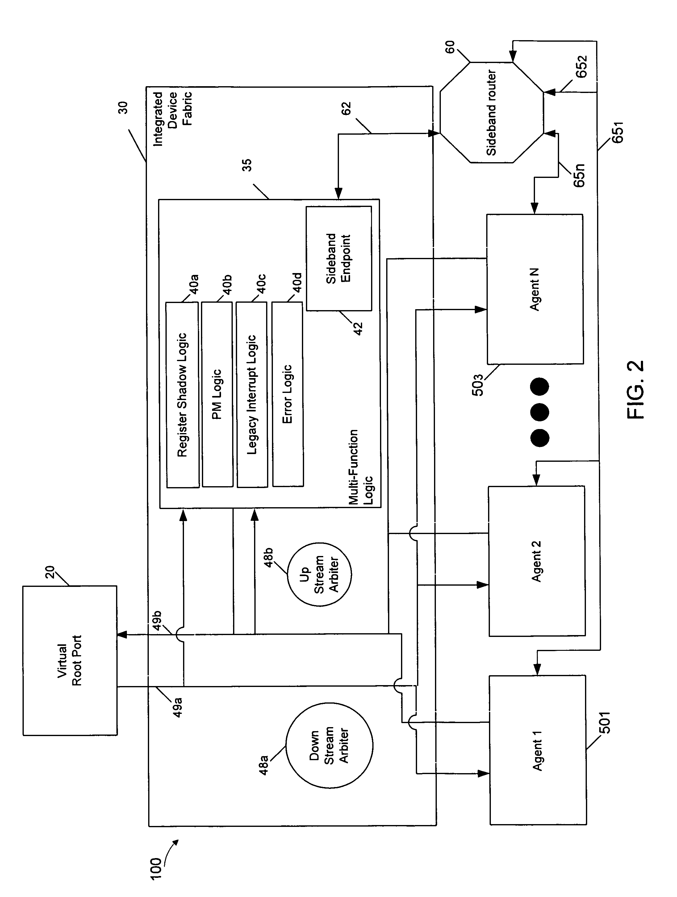
In various embodiments, interface functionality of a PCIe™ endpoint can be segmented between fabric logic and an agent such as an intellectual property (IP) block or other logic block configured to perform one or more functions, to enable efficient re-use of the agent across various platforms. As used herein, the terms “agent” and “IP block” may be synonymous to denote an independent logic that can be adapted within a semiconductor device along with other such agents, where the agents can originate with one or more vendors. For one implementation, such an agent can be implemented on-chip along with a virtual downstream port (root port or switch port) which may be a separate PCIe™ device, an integrated device fabric (IDF) containing multi-function (MF) logic, and one or more agents, which each can implement one or more PCI-e™ functions. In this way, one or more agents can be integrated into an on-die PCI-e™ device.

The virtual downstream port appears to software as a standard PCI-e™ d...


PUM


Abstract

An integrated endpoint having a virtual port coupled between an upstream fabric and an integrated device fabric that includes a multi-function logic to handle various functions for one or more intellectual property (IP) blocks coupled to the integrated device fabric. The integrated device fabric has a primary channel to communicate data and command information between the IP block and the upstream fabric and a sideband channel to communicate sideband information between the IP block and the multi-function logic.

Description

BACKGROUNDMainstream processor chips, both in high performance and low power segments, are increasingly integrating additional functionality such as graphics, display engines, security engines, PCIe™ ports (i.e., ports in accordance with the Peripheral Component Interconnect Express (PCI Express™ (PCIe™)) Specification Base Specification version 2.0 (published Jan. 17, 2007) (hereafter the PCIe™ specification) and other PCI-e™ based peripheral devices.Traditional peripheral hub product designs are highly segmented due to varying requirements from the server, desktop, mobile, embedded, ultra-mobile and mobile Internet device segments. Different markets seek to use single chip system-on-chip (SoC) solutions that combine at least some of processor cores, memory controller hub (MCH), input / output controller (ICH) and other segment specific acceleration elements onto a single chip. However, designs that accumulate these features are slow to emerge due to the difficulty of integrating dif...

Claims


Application Information

Patent Timeline
IPC IPC(8): H04L12/66G06F13/42
CPCH04L12/6418H04L12/1845G06F13/4027H04L67/1078H04L29/08468G06F13/4221G06F13/105G06F2213/0026H04L12/40032Y02D10/00
Inventor KLINGLESMITH, MICHAELNAIR, MOHANMURRAY, JOSEPH
Owner INTEL CORP
Why Eureka
Try Eureka