Ultrasonic diagnostic apparatus and ultrasonic transmission method

a diagnostic apparatus and ultrasonic technology, applied in diagnostics, medical science, instruments, etc., can solve the problems of residual echo, difficult to meet these requirements simultaneously, and inability to accurately measure blood flow velocity, etc., to achieve simple circuit configuration, reduce beam distortion of acoustic transmission/reception field or non-uniform transmission/reception sensitivity, good real-time property

Inactive Publication Date: 2011-01-25
TOSHIBA MEDICAL SYST CORP
View PDF4 Cites 5 Cited by
  • Summary
  • Abstract
  • Description
  • Claims
  • Application Information

AI Technical Summary

Benefits of technology

[0030]It is an object of the present invention to provide an ultrasonic diagnostic apparatus and an ultrasonic transmission method which decreases beam distortion of acoustic transmission / reception field and non-uniformity of transmission / reception sensitivity in simultaneous and parallel reception, using a simple circuit configuration.
[0033]In accordance with the aspect of the present invention, beam distortion of acoustic transmission / reception field or non-uniformity of transmission / reception sensitivity can be decreased with a simple circuit configuration. Accordingly, it is possible to generate ultrasonic image data showing a good real-time property and image quality so that diagnostic accuracy can be improved.

Problems solved by technology

When the Doppler frequency shift is greater than nyquist frequency, accurate measurement of blood flow velocity is not possible because of the aliasing occurred in a frequency spectrum of a Doppler signal.
Accordingly, there occurs a problem of a residual echo that reflected ultrasound corresponding to a preceded rate period are mixed and received.
Moreover, in order to improve the spatial resolution which is a third requirement, it is necessary to increase the number of transmission / reception directions N. That is, the frame frequency Fn, the low flow velocity detection capability Vmin, the high flow velocity detection capability Vmax, and the spatial resolution have trade-off relations each other, and thus it is difficult to satisfy these requirements simultaneously.
However, when the central axis of a transmitted ultrasonic beam and the central axis of a received ultrasonic beam are different in simultaneous and parallel reception method, the transmission / reception sensitivity is deteriorated.
Moreover, when the number of reception directions for the simultaneous and parallel reception is three or more, it is difficult to obtain uniform transmission / reception sensitivity in a lateral direction (a direction perpendicular to the transmission / reception direction of the ultrasounds).
However, as the focused transmitting ultrasound is used, it is difficult to enlarge the beam width so as to correspond to an acoustic reception field.
FIG. 14 shows the beam distortion which is a first problem of the conventional method or the method disclosed in U.S. Pat. No. 5,856,955, and FIG. 15 shows the non-uniformity in transmission / reception sensitivity which is a second problem of the above-mentioned method.
Accordingly, when the number of simultaneous reception directions is set to 3 or more, the amplitude of the acoustic transmission / reception field pattern (that is, transmission / reception sensitivity) is non-uniform in the lateral direction and dark and bright stripes are generated in the ultrasonic image data generated by the non-uniform transmission / reception field and deteriorates the image quality.
The remarkable decrease in transmission / reception sensitivity at the side portion of the acoustic transmission field makes it difficult to estimate flow velocity, variance, etc in the colored Doppler image data, as well as image quality deterioration in the B mode image data.
When the acoustic transmission pattern is enlarged in the lateral direction as shown in FIG. 14B for the purpose of improvement in the non-uniform transmission / reception sensitivity, ultrasonic transmission energy is uselessly irradiated to areas not associated with generation of image data, thereby transmission / reception sensitivity is deteriorated and generation of a virtual images (artifacts) due to side lobes and multiple reflections increase.

Method used


Image

  • Ultrasonic diagnostic apparatus and ultrasonic transmission method
  • Ultrasonic diagnostic apparatus and ultrasonic transmission method
  • Ultrasonic diagnostic apparatus and ultrasonic transmission method

Examples


first embodiment

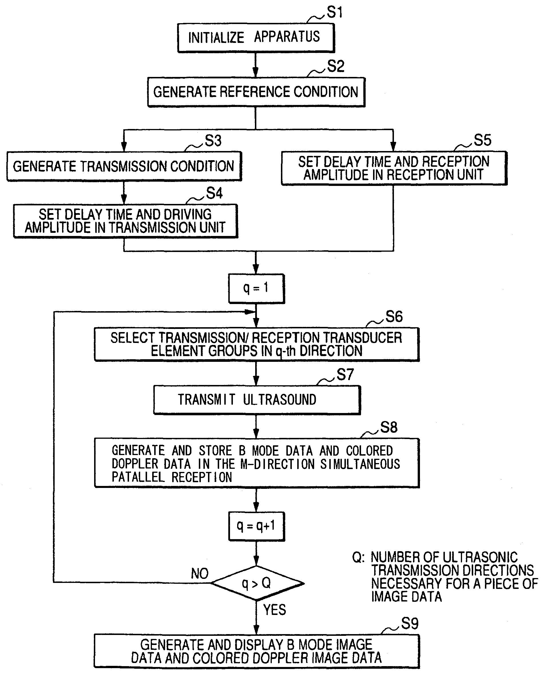
[0050]In the present invention described below, when simultaneous and parallel reception is performed using a convex scanning ultrasonic probe in which transducer elements are one-dimensionally arranged on a convex surface, an acoustic transmission field having uniform and suitable beam width in a lateral direction is formed by controlling delay time and driving amplitude of driving pulses (driving signals) supplied to a transmission transducer element group including a plurality of adjacent transducer elements.

[0051]In this case, the transmission conditions (transmission delay condition and transmission amplitude condition) for determining the delay time and the driving amplitude of driving pulses supplied to the transducer elements of the transmission transducer element group is set on the basis of the reference conditions (reference delay condition and reference amplitude condition) in a non-simultaneous and parallel reception using the transmission transducer element group.

[0052...

second embodiment

[0148]As described above, an acoustic transmission field substantially equivalent to the acoustic transmission field shown in FIG. 7 can be obtained by driving the transducer elements P1 to PM0 by the driving pulse Hp(m) based on the transmission delay condition τp(m) and the transmission amplitude condition Ap(m) generated by Expression 9. However, in the second embodiment, the lateral direction X in FIG. 7 is substituted with the angle θ and ΔM is substituted with Δθ.

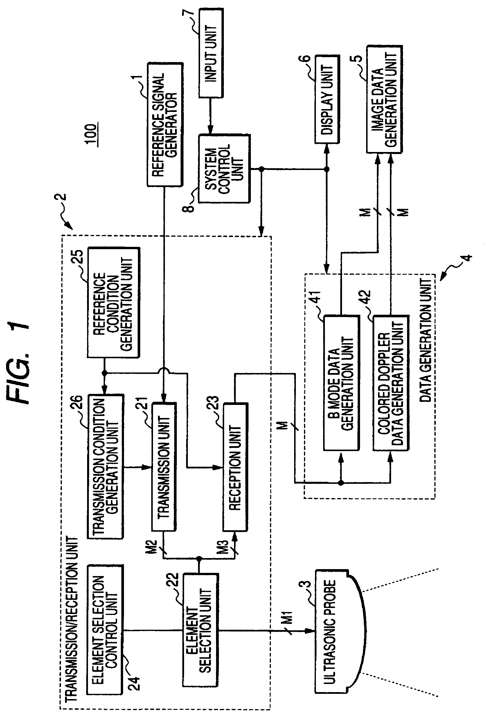
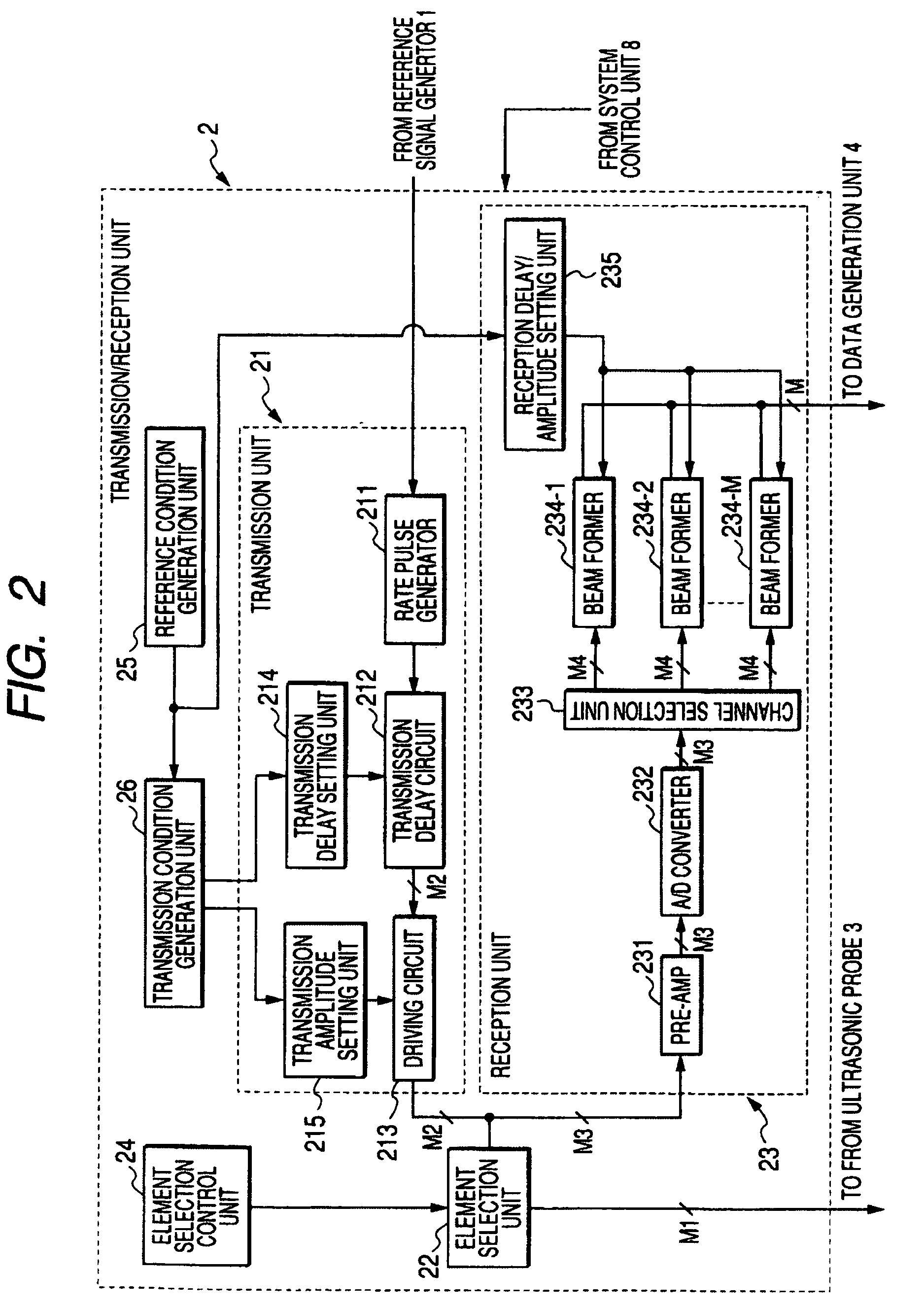
[0149]That is, the transmission condition generation unit 26a generates the transmission delay condition τp(m) and the transmission amplitude condition Ap(m) through the above-mentioned calculations using the reference delay condition τpo(m) and the reference amplitude condition Ao(m) for transmission supplied from the reference condition generation unit 25a, and supplies the result to the transmission delay setting unit 214a and the transmission amplitude setting unit 215a of the transmission unit 21a. The transmissi...


PUM


Abstract

A reference condition generation unit of an ultrasonic diagnostic apparatus generates a reference delay condition and a reference amplitude condition for determining delay time and amplitude of a driving pulse to be supplied to a transducer element at the time of non-simultaneous and parallel reception. A transmission condition generation unit generates a transmission delay condition and a transmission amplitude condition for determining delay time and amplitude of a driving pulse to be supplied to a transducer element at the time of simultaneous and parallel reception, on the basis of the reference delay condition and the reference amplitude condition. A transmission unit sets the delay time and the driving amplitude of the driving pulse to be supplied to a plurality of adjacent transducer elements selected by an element selection unit among the transducer elements arranged in an ultrasonic probe, on the basis of the transmission delay condition and the transmission amplitude condition.

Description

CROSS-REFERENCE TO RELATED APPLICATIONS[0001]This application is based upon and claims the benefit of priority from the prior Japanese Patent Application No.2005-230300 filed on Aug. 9, 2005, the entire contents of which are incorporated herein by reference.FIELD OF THE INVENTION[0002]The present invention relates to an ultrasonic diagnostic apparatus and an ultrasonic transmission method, and more particularly, to an ultrasonic diagnostic apparatus and an ultrasonic transmission method to perform receiving reflected ultrasound simultaneously from a plurality of directions simultaneously.DESCRIPTION OF THE BACKGROUND[0003]An ultrasonic diagnostic apparatus is designed to generate ultrasonic pulses from transducer elements disposed in an ultrasonic probe. The ultrasonic pulses are emitted into an object to be examined. The ultrasonic diagnostic apparatus receives reflected ultrasound produced due to differences in acoustic impedance among the tissues of the object. The ultrasonic dia...

Claims


Application Information

Patent Timeline
Patent Type & Authority Patents(United States)
IPC IPC(8): A61B8/00
CPCA61B8/06A61B8/13G01S7/52023A61B8/4494
Inventor SHIKI, EIICHI
Owner TOSHIBA MEDICAL SYST CORP
Why Eureka
Try Eureka