Prosthetic element

a technology of prosthetic elements and elements, applied in the field of prosthetic elements, can solve the problems of undesirable bone remodeling, inability to hinder micro-motion at the element/tissue interface, and indented or raised portions

Inactive Publication Date: 2011-01-25
AARBAKKE MEDICAL AS
View PDF29 Cites 35 Cited by
  • Summary
  • Abstract
  • Description
  • Claims
  • Application Information

AI Technical Summary

Benefits of technology

[0043]FIG. 5 Diagrams illustrating the effect of the invention when using the embodiment according to a test stem, in principle, designed as FIG. 4.

Problems solved by technology

Consequently, such elements may be quite difficult to retrieve.
However, such indented or raised portions cannot hinder micro-motion at the element / tissue interface.
Moreover, such instability leads to undesirable bone remodeling.
Such designs have therefore given poor results in patients.
But the more rough the surface, the more difficult the retrieval.
Thus, the retrieval of a rough-surfaced element can be very cumbersome.
And loss of essential bone stock is inevitable.
Such a method has several disadvantages like adversely affecting the properties of the material, difficulties to control the surface geometry of the ball coated implant, and surface balls can migrate from the implant causing severe third body wear in the artificial joint proper.
Further, the removal of a totally ball coated hip or shoulder joint stem can be disastrous; even if a major part of the bone is temporarily removed, there is the risk of breaking the bone in several pieces.
Although a collar obstructing the access to the stem below is provided only medially in the above inventions, removing such implants can be very difficult.
And loss of essential bone stock is inevitable.
But such anchorage cannot hinder undesirable micro-motion at the bone / tissue interface.
A collar naturally obstructs the access to the stem below.
Thus, to remove the anchorage a quite large access may be needed, the larger the more loss of bone stock.
Naturally, the more anchoring holes the better the fixation, but the more difficult the retrieval if deemed necessary.
Although some of this spongy material might be removed from the hollow space of the prostheses, this procedure alone does not loosen the prosthesis sufficiently to be able to remove the prosthesis from the femur.
This operation has features similar to the method used for the totally ball coated stem described above, and results in a relatively extensive loss of bone stock.
This access slot gives access to the proximal part of the stem, but using a saw or chisel onto the outside of a prosthetic element will inevitably lead to loss of bone stock.
However, as outlined above, such large bone block anchorage cannot hinder undesirable micro-mobility at the implant / bone interface.
Second, on retrieval, the chisel (or saw), inevitable destroys bone stock.
The more distal the cutting, the more bone stock loss.
If not, the femur will crack.
So these guides can only be used in the upper part of a curved prosthetic element.
And as outlined above, using a cutting tool into the interface between prosthesis and the surrounding bone will inevitably lead to loss of bone stock, or the bone will crack.
A possible removal of the prosthetic element would cause considerable loss of bone.
The space between the longitudinal ribs may provide some guidance for the cutting tool, but the shape of these spaces does not provide protection so as to minimize the loss of bone stock.
But the better the anchorage, the more difficult the retrieval.
And retrieval of the above prosthetic designs inevitable lead to loss of bone stock, or the bone will break in two or more pieces, or both.
Such alternatives are undesirable.

Method used


Image

  • Prosthetic element
  • Prosthetic element
  • Prosthetic element

Examples


Embodiment Construction

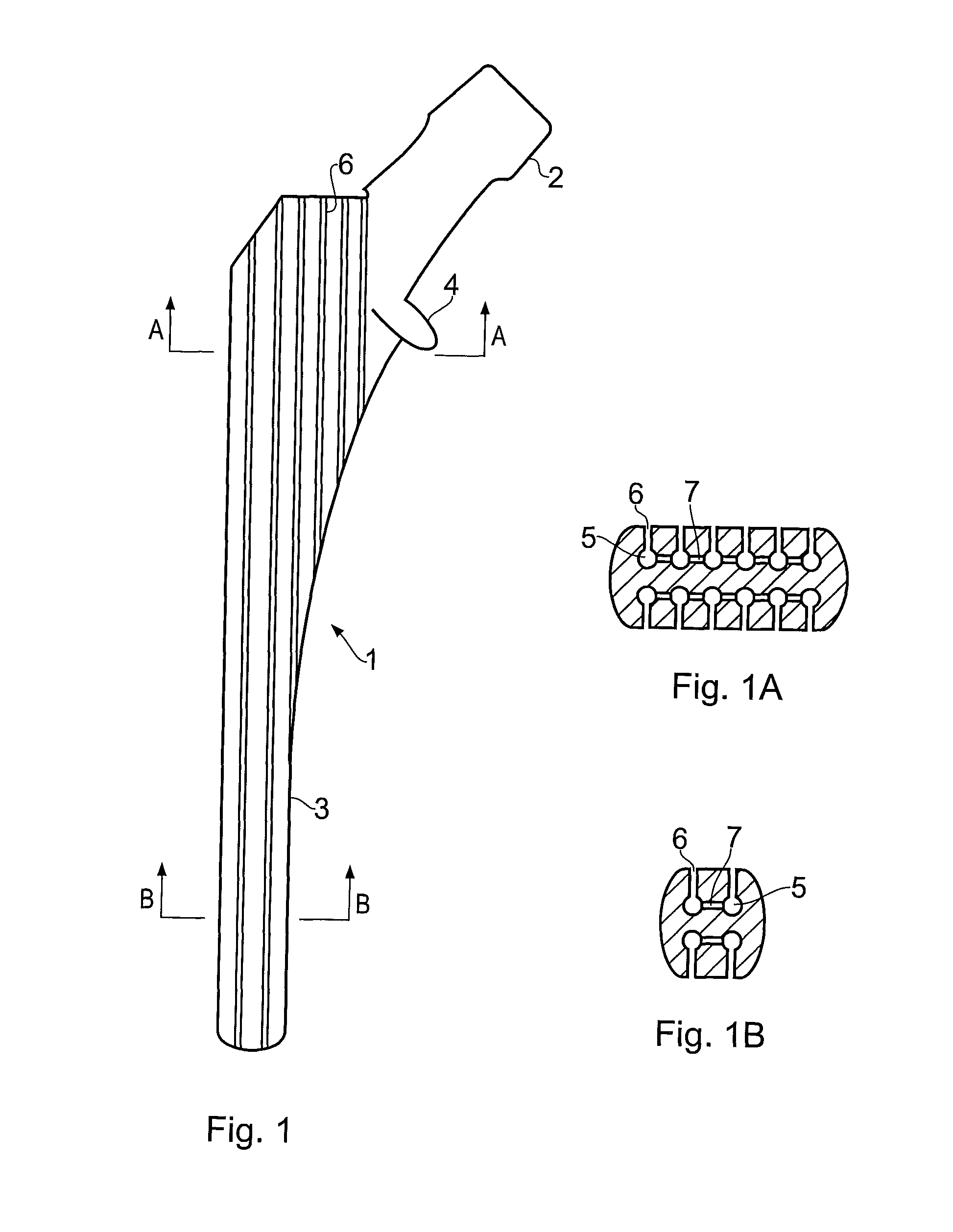
[0049]Although this description focuses on the application of the invention to a proximal femoral prosthesis, the invention is equally applicable to other types of cementless or cemented prosthesis. That is, the cutting guide means may be applied to other types of devices having different geometries.

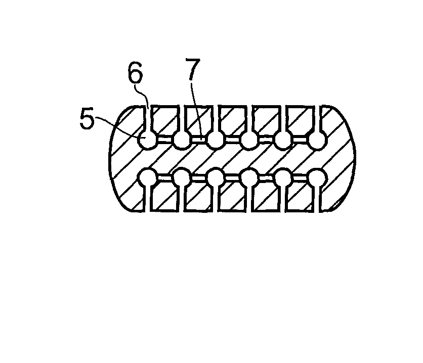
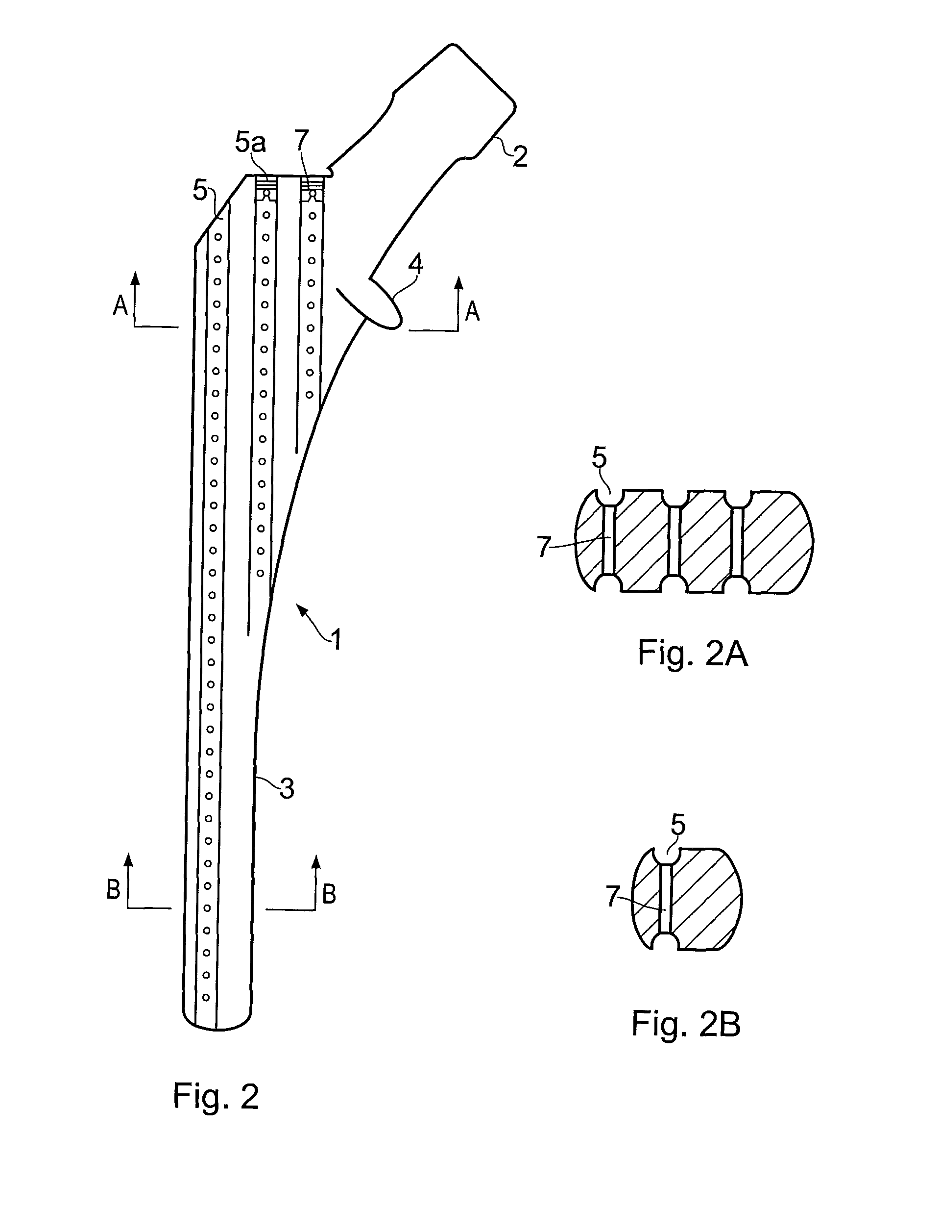
[0050]According to one aspect of the invention as seen in FIG. 1, the prosthesis comprises an elongated stem having a smooth outer surface, a portion of which defines, when the element is implanted in a subject, a contact interface between the stem and surrounding bone and / or fibrous tissue. The prosthesis has one or more longitudinal guide channels located to the interior of the outer surface of the stem, and each of said channel or channels have an at least semi-circular wall portion. The radius of curvature of the at least semi-circular wall portion is adapted for receiving and laterally retaining a drill bit. According to one aspect of the invention the guide channels are longitudina...


PUM

PropertyMeasurementUnit
diameteraaaaaaaaaa
diameteraaaaaaaaaa
lengthaaaaaaaaaa

Abstract

The invention concerns a prosthetic element (1) with an outer surface defining an interface to the surrounding bone or fibrous tissue, wherein the prosthetic element (1) is provided with at least one internal anchoring cavity (6) for the growing of tissue and a least one guide means (5) for a cutting tool. The guide means (5) and the anchoring cavities (6) are positioned essentially within the perimeter / circumference of the prosthetic element (1) defined by the outer surface of the prosthetic element (1). The anchoring cavities (6) and the guide means (5) are interconnected and at least one of the anchoring cavities (6) and / or the guide means (5) has an opening in the outer surface for the growing of tissue into the element (1).

Description

FIELD OF THE INVENTION[0001]This invention relates generally to a prosthetic element. The prosthetic element according to the invention is applicable in joint-replacement surgery, wherein methods for the anchorage of the prosthetic element to living tissue like bone to be utilized. The configuration of the prosthetic element, according to the invention, facilitates the removal of the prosthetic element if deemed necessary.BACKGROUND OF THE INVENTION[0002]Prosthetic elements, like joint-replacement surgery in larger synovial joints like the hip, knee or the shoulder, can be anchored to the bone either by bone cement, or by cementless fixation like press fit, or anchorage by fibrous and bone ongrowth, or ingrowth in pores. As for now, fixation with bone cement has given the best long-term results both in the elderly as well in younger patients. Consequently, more cementless elements than cemented ones have been removed and subsequently the need for adequate replacement surgery is esse...

Claims


Application Information

Patent Timeline
Patent Type & Authority Patents(United States)
IPC IPC(8): A61F2/36A61B17/16A61B17/17A61C8/00A61F2/00A61F2/30A61F2/32A61F2/34A61F2/38A61F2/40A61F2/42A61F2/46
CPCA61B17/17A61C8/0006A61C8/0018A61F2/30767A61F2/30771A61F2/36A61B17/16A61B17/1668A61B17/175A61F2/30744A61F2/32A61F2/34A61F2/38A61F2/3804A61F2/40A61F2/4202A61F2/4607A61F2002/30179A61F2002/30332A61F2002/30405A61F2002/30596A61F2002/30677A61F2002/307A61F2002/30774A61F2002/30785A61F2002/30787A61F2002/30789A61F2002/30828A61F2002/30846A61F2002/3625A61F2002/3631A61F2002/3643A61F2002/365A61F2002/368A61F2002/3686A61F2002/3694A61F2002/3696A61F2002/4619A61F2002/4631A61F2220/0025A61F2220/0033A61F2230/0058A61F2250/0081A61F2310/00796A61F2002/30594A61F2002/30845A61F2002/30772A61F2/30A61C8/00
Inventor SUDMANN, EINAR
Owner AARBAKKE MEDICAL AS
Why Eureka
Try Eureka