Disk drive updating estimate of voice coil resistance to account for resistance change prior to unload operation

a technology of voice coil and unloading operation, applied in the direction of magnetic recording, data recording, instruments, etc., can solve the problems of damage to the head, and inability to accurately estimate the initial estima

Active Publication Date: 2011-01-25
WESTERN DIGITAL TECH INC
View PDF32 Cites 121 Cited by
  • Summary
  • Abstract
  • Description
  • Claims
  • Application Information

AI Technical Summary

Problems solved by technology

For example, if the resistance is estimated prior to a load operation using a suitable calibration technique, the resistance may change over time such that the initial estimate is no longer reliable during an unload operation.
The error in the estimated resistance may have undesirable effects, such as damaging the head due to an excessive unload velocity, or failure of the unload operation due to insufficient unload velocity.

Method used


Image

  • Disk drive updating estimate of voice coil resistance to account for resistance change prior to unload operation
  • Disk drive updating estimate of voice coil resistance to account for resistance change prior to unload operation
  • Disk drive updating estimate of voice coil resistance to account for resistance change prior to unload operation

Examples


Embodiment Construction

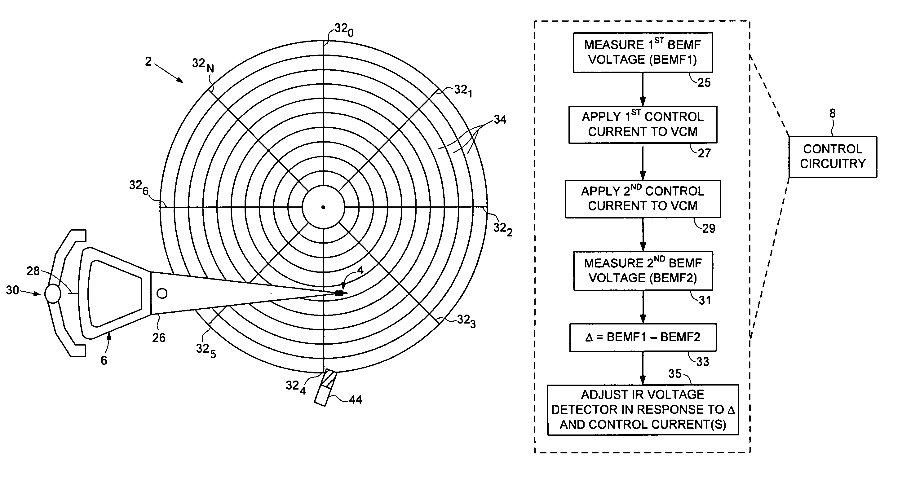
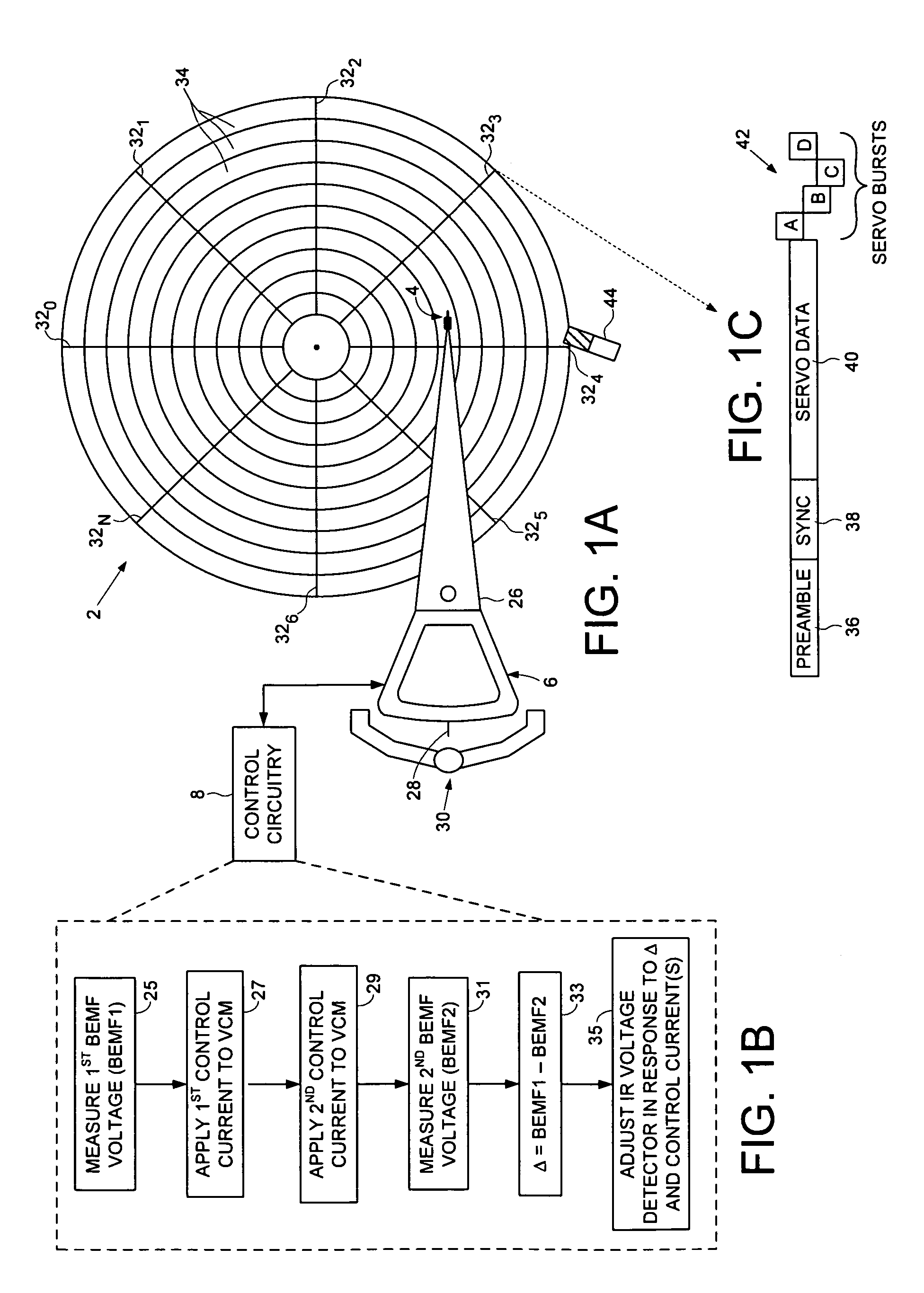
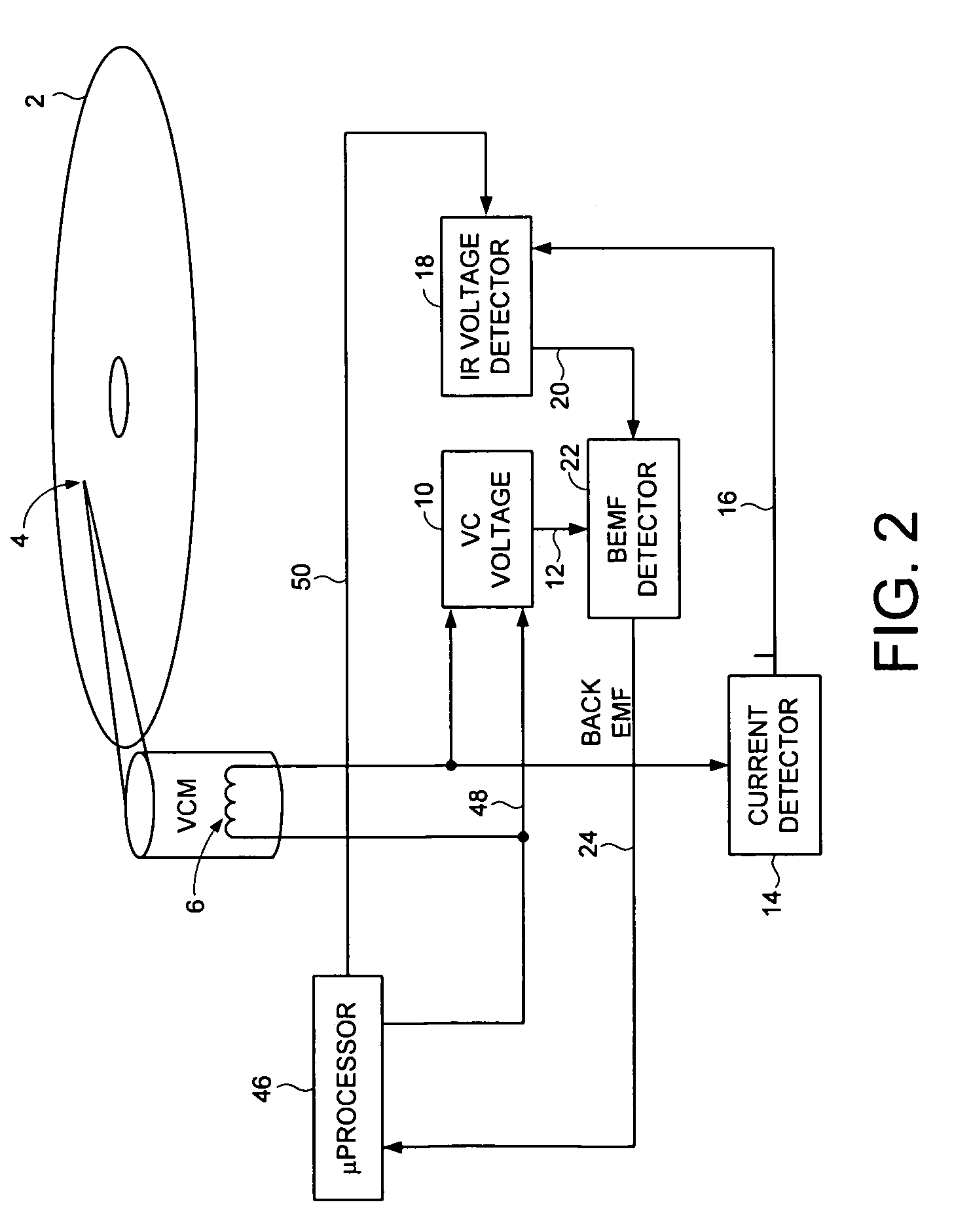
[0016]FIG. 1A shows a disk drive according to an embodiment of the present invention comprising a disk 2, a head 4, and a voice coil motor (VCM) comprising a voice coil 6 operable to actuate the head 4 radially over the disk 2. The disk drive comprises control circuitry 8 including a VCM control loop (FIG. 2) comprising a voltage detector 10 operable to detect a voice coil voltage 12 across the voice coil 6. A current detector 14 detects a current 16 flowing through the voice coil 6, and an IR voltage detector 18, responsive to the detected current 16, operable to detect a resistive voltage 20 due to a resistance of the voice coil 6. A back EMF detector 22 subtracts the resistive voltage 20 from the voice coil voltage 12 to generate a back EMF voltage 24.

[0017]The control circuitry 8 executes the flow diagram of FIG. 1B to update the IR voltage detector 18. A first back EMF voltage is measured (step 25), and after measuring the first back EMF voltage, a first control current is appl...


PUM

PropertyMeasurementUnit
currentaaaaaaaaaa
voltageaaaaaaaaaa
voltage detectoraaaaaaaaaa

Abstract

A disk drive is disclosed comprising a disk and a head actuated over the disk by a voice coil motor (VCM) comprising a voice coil, wherein the VCM is controlled by a VCM control loop comprising an IR voltage detector. The IR voltage detector is updated by measuring a first back EMF voltage of the voice coil, and after measuring the first back EMF voltage, applying a first control current to the voice coil for a first interval and applying a second control current to the voice coil for a second interval. After the second interval, a second back EMF voltage is measured, and a delta voltage is computed relative to a difference between the first back EMF voltage and the second back EMF voltage. The IR voltage detector is adjusted in response to the delta voltage and at least one of the first and second control currents.

Description

BACKGROUNDDescription of the Related Art[0001]Disk drives comprise a disk and a head connected to a distal end of an actuator arm which is rotated about a pivot by a voice coil motor (VCM) to position the head radially over the disk. The disk comprises a plurality of radially spaced, concentric tracks for recording user data sectors and embedded servo sectors. The embedded servo sectors comprise head positioning information (e.g., a track address) which is read by the head and processed by a servo control system to control the velocity of the actuator arm as it seeks from track to track.[0002]There are times when the servo control system does not have access to the embedded servo sectors yet it is still desirable to control the velocity of the actuator arm. For example, in disk drives employing ramp loading / unloading, it is desirable to control the velocity of the actuator arm so that the head is not damaged as it travels off the ramp onto the disk as well as off the disk onto the r...

Claims


Application Information

Patent Timeline
Patent Type & Authority Patents(United States)
IPC IPC(8): G11B5/54G11B21/12
CPCG11B5/54G11B21/12
Inventor CALAWAY, CHARLES J.DESAI, ASHOK K.
Owner WESTERN DIGITAL TECH INC
Why Eureka
Try Eureka