Current-magnitude-based open-circuit failure online-diagnosis method for power tube of inverter

A technology of open circuit fault and diagnosis method, which is applied in the direction of controlling electromechanical brakes, electrical components, controlling generators, etc., can solve problems such as poor robustness, and achieve good robustness

CN103701394AInactive Publication Date: 2014-04-02HARBIN INST OF TECH
8 Cites 85 Cited by

Patent Information

Authority / Receiving Office
CN · China
Current Assignee / Owner
Publication Date
2014-04-02
Estimated Expiration
Not applicable · inactive patent

Smart Images

  • Figure 1
    Figure 1
  • Figure 2
    Figure 2
  • Figure 3
    Figure 3
Patent Text Reader

Abstract

The invention discloses a current-magnitude-based open-circuit failure online-diagnosis method for a power tube of an inverter, belongs to the field of motor control, and aims to solve the problem of poor robustness of a current-magnitude-based open-circuit failure diagnosis technology for the power tube of the inverter. The method comprises the following steps of establishing a current observer model of a permanent magnet synchronous motor driving system in a failure-free state, comparing an observed current value with detection current to obtain a three-phase current residual, converting the three-phase current residual to a two-phase coordinate system in a coordinate conversion way to obtain a current residual vector, standardizing the current residual vector, and diagnosing and positioning an open-circuit failure of the power tube of the inverter according to the amplitude and the phase of the standardized current residual vector. The current-magnitude-based open-circuit failure online-diagnosis method for the power tube of the inverter is free of influence of a system closed-loop control algorithm and insensitive to loads, and has higher robustness to parameter errors, measurement errors, system disturbance and the like.
Need to check novelty before this filing date? Find Prior Art

Description

technical field

[0001] The invention relates to an on-line diagnosis method for an open-circuit fault of an inverter power tube based on the amount of current, and belongs to the field of motor control. Background technique

[0002] The permanent magnet synchronous motor drive system powered by voltage source inverter has been widely used in industry, electric vehicles, military, aerospace and other fields due to its superior performance and high efficiency. However, due to the fragility of power electronic devices and their driving circuits, the inverter becomes a weak link in the system that is prone to failure. After the inverter fails, it will work in an abnormal state, which will cause the output torque of the motor to decrease and fluctuate, affect the system performance, and increase the voltage and current stress of other components. In severe cases, the system will collapse, so timely diagnosis is required. The short circuit and open circuit of the power switch tub...

Examples

specific Embodiment approach 1

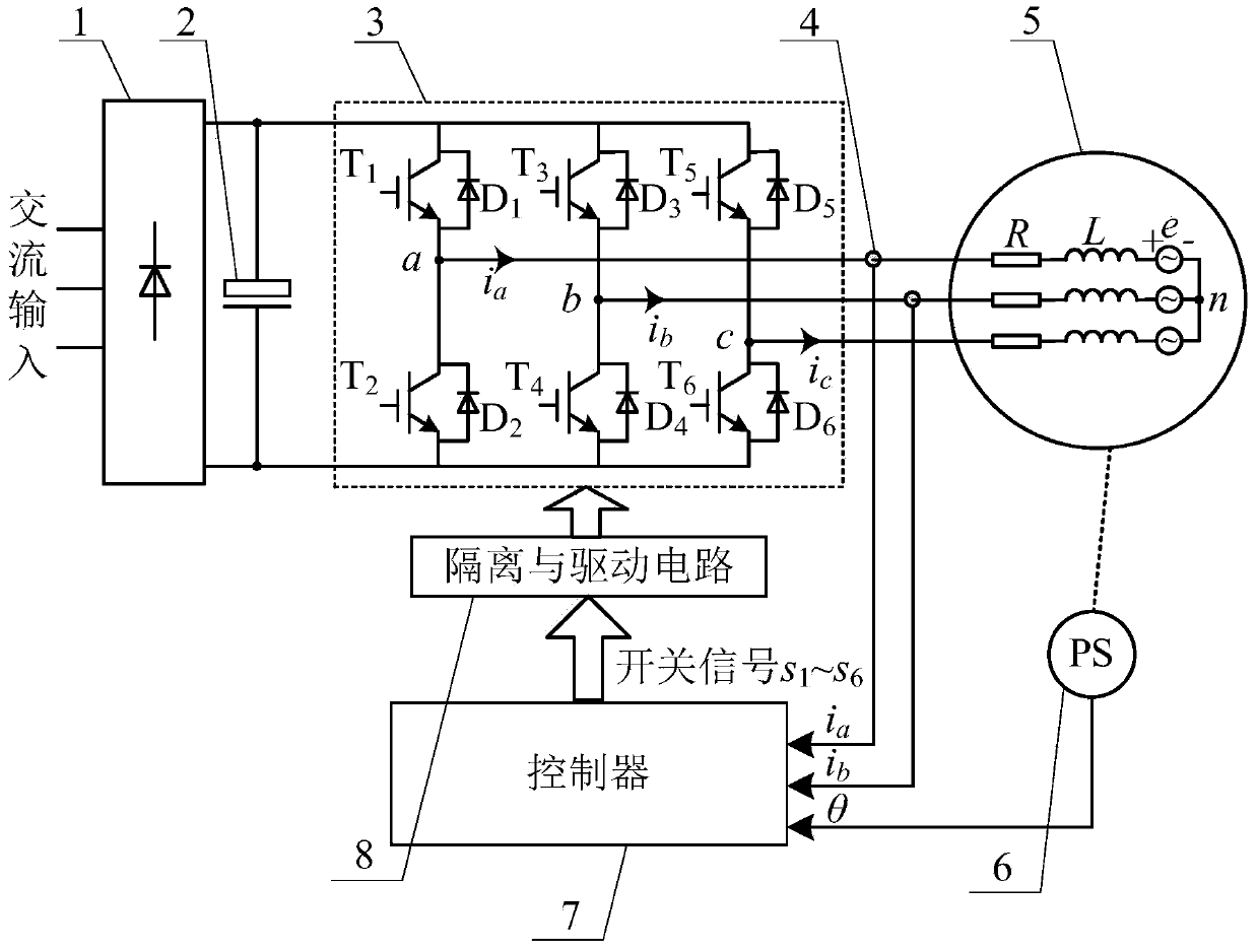
[0035] Specific implementation mode one: the following combination Figure 1 to Figure 5 This embodiment is described. The current-based online diagnosis method for the open circuit fault of the inverter power tube is described in this embodiment. The permanent magnet synchronous motor drive system involved in the method includes a rectifier 1, a DC filter capacitor 2, and an inverter 3. , current sensor 4, permanent magnet synchronous motor 5, position sensor 6, controller 7 and isolation and drive circuit 8; as figure 1 shown;

[0036] Inverter 3 consists of power tube T 1 , T 2 ,...,T 6 Composed of, the phase A bridge arm is composed of T 1 and T 2 Constituted, the B-phase bridge arm is composed of T 3 and T4 Constituted, the C-phase bridge arm is composed of T 5 and T 6 pose, T 1 , T 3 and T 5 is the upper bridge arm, T 2 , T 4 and T 6 is the lower bridge arm;

[0037] The DC output terminal of the rectifier 1 is connected in parallel with the DC filter capa...

specific Embodiment approach 2

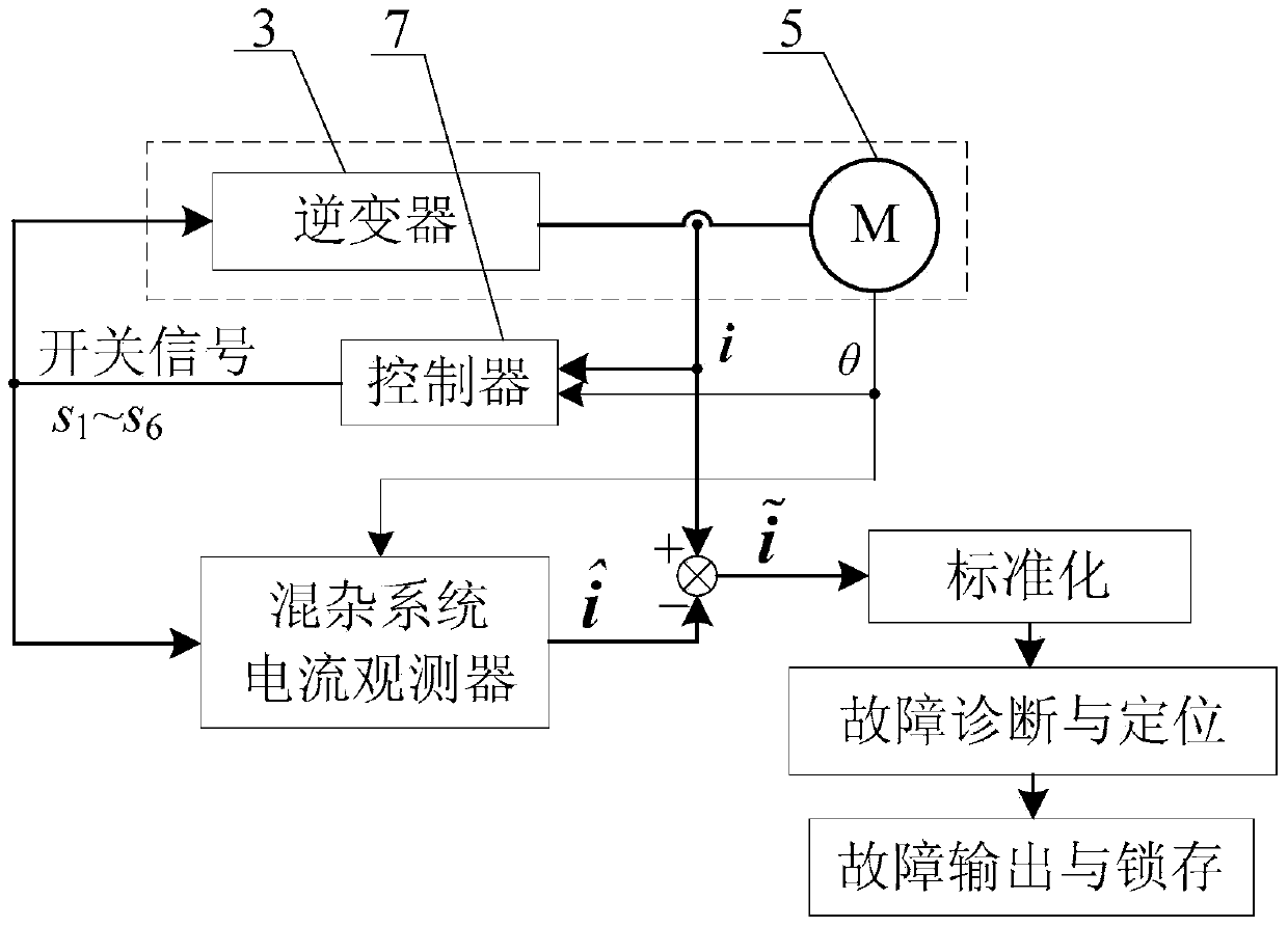
[0059] Specific implementation mode two: this implementation mode further explains implementation mode one. In step one, a hybrid system current observer is used to observe the current signal of the permanent magnet synchronous motor 5, and obtain the current observation value i ^ = i ^ a i ^ b i ^ c T , The process is:

[0060] by model Observing the current signal of the permanent magnet synchronous motor 5,

[0061] in: for d...

specific Embodiment approach 3

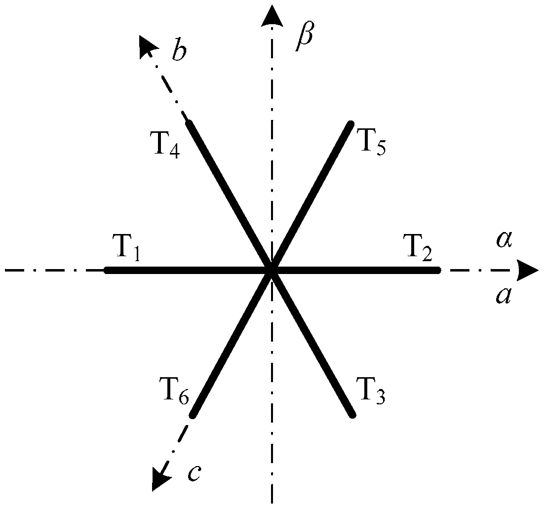
[0068] Specific implementation mode 3: This implementation mode further explains the implementation mode 1. In step 3, the α-axis current residual β axis current residual Obtained according to the following formula:

[0069] i ~ α i ~ β = 2 3 1 - 1 2 - 1 2 0 3 / ...