Lane marker detection and fitting methods

a technology of lane marker and fitting method, which is applied in the direction of vehicle position/course/altitude control, process and machine control, instruments, etc., can solve the problems of difficult in practice, common conditions can continue for a considerable time, and it is difficult for an imaging system to accurately determine the position of lane marker and vehicl

Active Publication Date: 2011-01-25
APTIV TECH LTD
View PDF12 Cites 25 Cited by
  • Summary
  • Abstract
  • Description
  • Claims
  • Application Information

AI Technical Summary

Benefits of technology

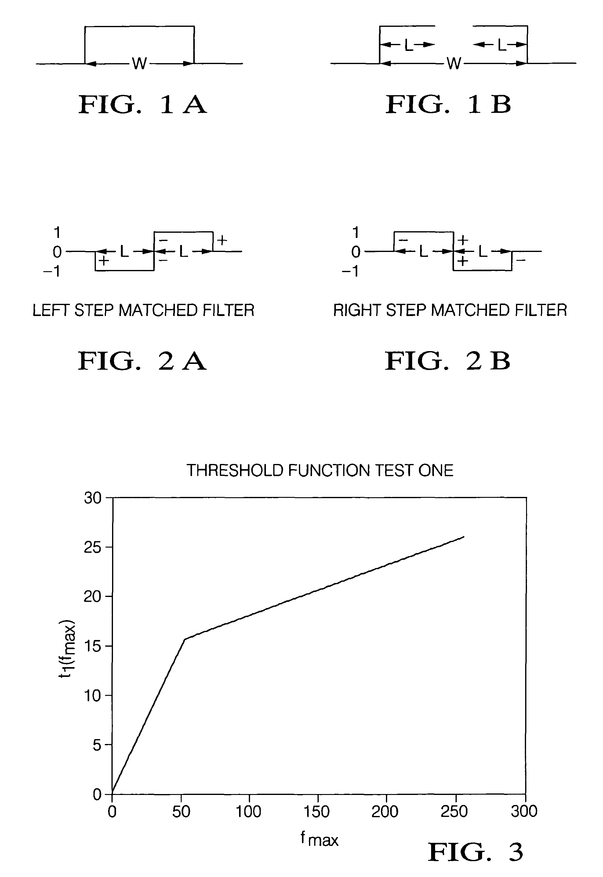
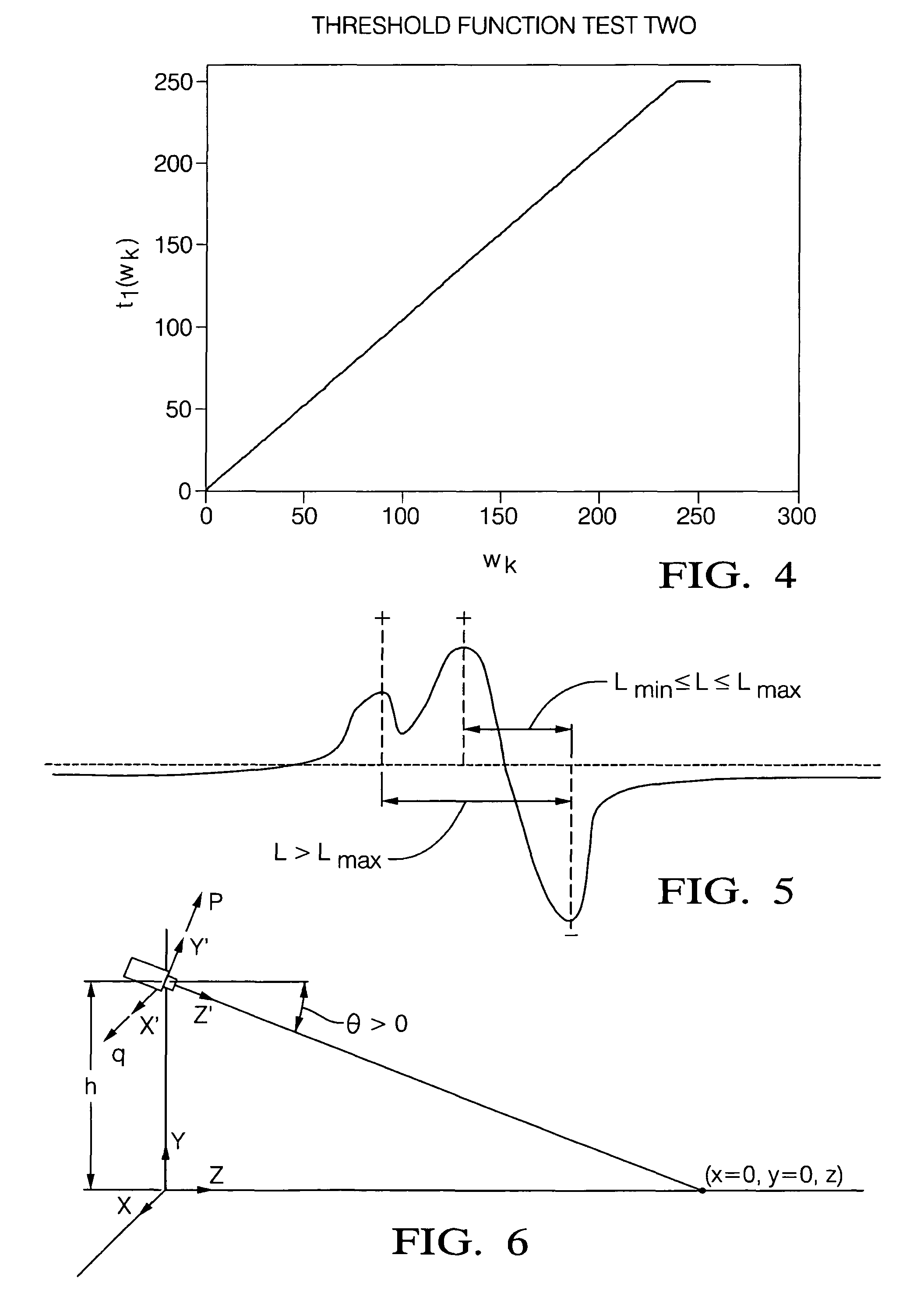
[0007]A lane marker matched filter response is peak detected for both positive and negative peaks. In an embodiment, to be considered a peak, a lane marker response has a magnitude above a threshold and is a local peak in a five point neighborhood centered about a point, as described infra. Thresholding is based on measurements from collected road images and is based on two tests. A normalized difference between a left and a right side has a magnitude above a threshold that is a function of estimated illumination, and the average brightness of the brighter side, presumed to be a lane marker, is brighter than an inside neighborhood brightness (road without a lane marker). The present also provides efficient algorithms to match “best” left and right edge detections of a potential marker detection. A minimum lane marker width and a maximum lane marker width are also transformed to a width in pixels for each row of an image.

Problems solved by technology

However, this is very difficult in practice.
For example, a variety of lighting conditions commonly occur that make it much more difficult for an imaging system to accurately determine lane markers and vehicle position.
One example of a common difficult imaging condition is bright sunlight where the glare off a tar seam can emit a brighter image than a true lane marker.
These common conditions can continue for a considerable time, necessitating lane tracking systems to consider various road conditions.
Such approaches to solving the problem are complex and have proven costly, in both design and implementation.

Method used


Image

  • Lane marker detection and fitting methods
  • Lane marker detection and fitting methods
  • Lane marker detection and fitting methods

Examples


Embodiment Construction

[0030]Exemplary embodiments are described with reference to specific configurations. Those of ordinary skill in the art will appreciate that various changes and modifications can be made while remaining within the scope of the appended claims. Additionally, well-known elements, devices, components, methods, process steps and the like may not be set forth in detail in order to avoid obscuring the invention. Further, unless indicated to the contrary, the numerical values set forth in the following specification and claims are approximations that may vary depending upon the desired characteristics sought to be obtained by the present invention.

[0031]A method and system is described herein for providing lane marker detection and modeling, and fitting a straight or curved lane marker to a collection of potential lane marker objects in a camera image, for vehicle occupant safety and other applications. The present invention takes into account complicating real world considerations includi...


PUM


Abstract

A method of lane marker detection and detection fitting is provided for lane tracking. A lane marker is modeled and split into left and right steps. A filter response is calculated from a cumulative row sum, and normalized for filter pixel size, lane marker brightness and road brightness. A lane marker response is peak detected for positive and negative peaks and checked for having a magnitude above a threshold and being a local peak in a five point neighborhood. A Hough transform is extended to multiple planes to use lane marker features to determine a best line. Lane marker features include a mean and variance of lane marker brightness, lane marker width, lane marker parallelism to a host vehicle direction of travel, and consistence with a predicted lane marker characteristic. A closest lane marker line to a host vehicle is identified, and refitted to account for any curvature.

Description

FIELD OF THE INVENTION[0001]The invention relates generally to lane tracking for vehicle safety and other applications, and more particularly to lane marker detection and fitting a straight or curved lane marker to a collection of potential lane marker objects in a camera image.BACKGROUND OF THE INVENTION[0002]Automated safety features for motor vehicles have been proposed and developed in recent years. Vision based lane tracking systems have been designed that are supposed to monitor a vehicle position by imaging a roadway and detecting lane markers. These lane tracking systems can be used for lane departure warning, or in more advanced systems may even be used for lane keeping assistance or automated vehicle guidance systems. In such lane tracking systems, a camera captures images of a roadway in front of a vehicle and imaging processing software identifies the lane markers from the roadway. The vision system can then determine the vehicle position relative to the lane markers, fo...

Claims


Application Information

Patent Timeline
Patent Type & Authority Patents(United States)
IPC IPC(8): G05D1/00G06K9/00
CPCG06K9/00798G06K9/4609G06V20/588G06V10/443
Inventor SCHWARTZ, DAVID A.SCHIFFMANN, JAN K.HAMILTON, LISA R.
Owner APTIV TECH LTD
Why Eureka
Try Eureka