

Method and system for mapping enterprise data assets to a semantic information model
a data asset and semantic information technology, applied in the field of data schema, can solve the problem that data cannot be easily imported or exported from one application to another, and achieve the effect of facilitating data import and expor
- Summary
- Abstract
- Description
- Claims
- Application Information
AI Technical Summary
Benefits of technology
Problems solved by technology
Method used
Image

Examples
examples
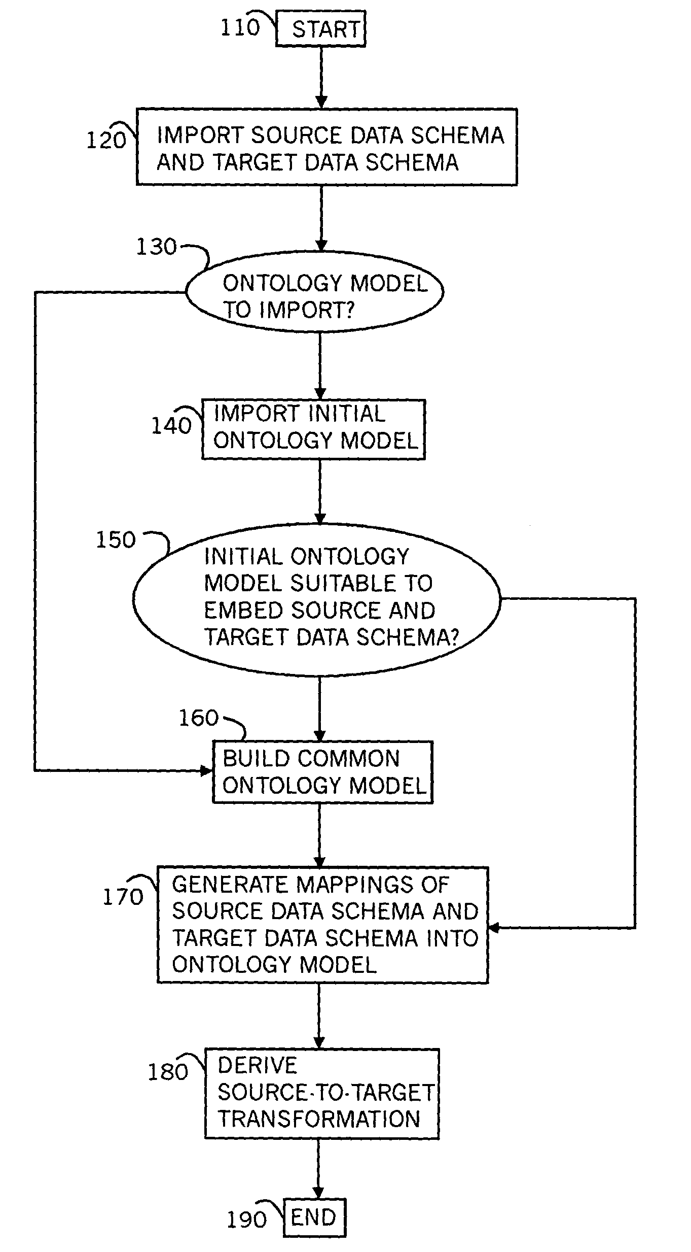
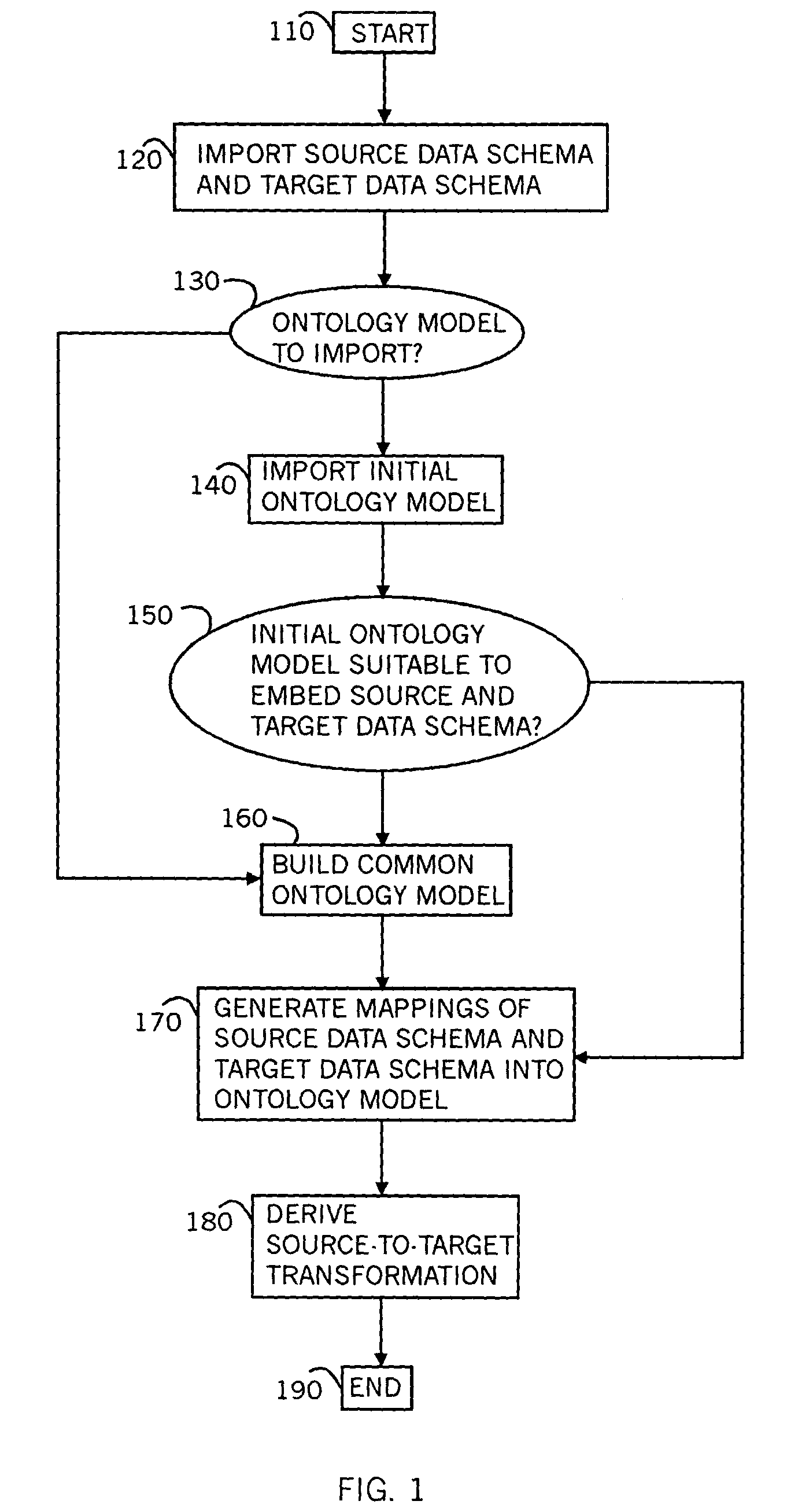
[0196]For purposes of clarity and exposition, the workings of the present invention are described first through a series of twenty-three examples, followed by a general description of implementation. Two series of examples are presented. The first series, comprising the first eleven examples, relates to RDBS transformations. For each of these examples, a source RDBS and target RDBS are presented as input, along with mappings of these schema into a common ontology model. The output is an appropriate SQL query that transforms database tables that conform to the source RDBS, into database tables that conform to the target RDBS. Each example steps through derivation of source and target symbols, expression of target symbols in terms of source symbols and derivation of an appropriate SQL query based on the expressions.
[0197]The second series of examples, comprising the last twelve examples, relates to XSLT transformation. For each of these examples, a source XML schema and target XML sch...
sixth example
A Sixth Example
[0303]In a sixth example, a target table is of the following form:
[0304]
TABLE LIIITarget Table T for Sixth ExampleIDNameDogs_Previous_Owner
[0305]Two source tables are given as follows:
[0306]
TABLE LIVSource Table S1 for Sixth ExampleIDNameDog
[0307]
TABLE LVSource Table S2 for Sixth ExampleOwnerNamePrevious_Owner
[0308]The underlying ontology is illustrated in FIG. 16. The dotted portions of the ontology in FIG. 16 are additional ontology structure that is transparent to the relational database schema. The unique properties of the ontology are:
[0309]
TABLE LVIUnique Properties within Ontology for Sixth ExamplePropertyProperty IndexID#(Person)2name(Dog)6
[0310]The mapping of the target schema into the ontology is as follows:
[0311]
TABLE LVIIMapping from Target schema to Ontology for Sixth ExamplePropertyschemaOntologyIndexTClass: PersonT.IDProperty: ID#(Person)2T.NameProperty: name(Person)1T.Dogs_Previous—Property: previous_owner(dog(Person))5o3Owner
[0312]The mappin...
seventh example
A Seventh Example
Employees
[0320]In a seventh example, a target table is of the following form:
[0321]
TABLE LXITarget Table T for Seventh ExampleIDNameEmailDepartment
[0322]Five source tables are given as follows:
[0323]
TABLE LXIISource Table S1 for Seventh ExampleIDDepartment
[0324]
TABLE LXIIISource Table S2 for Seventh ExampleIDEmail
[0325]
TABLE LXIVSource Table S3 for Seventh ExampleIDName
[0326]
TABLE LXVSource Table S4 for Seventh ExampleIDEmail
[0327]
TABLE LXVISource Table S5 for Seventh ExampleIDDepartment
[0328]The underlying ontology is illustrated in FIG. 17. The dotted portions of the ontology in FIG. 17 are additional ontology structure that is transparent to the relational database schema. The unique properties of the ontology are:
[0329]
TABLE LXVIIUnique Properties within Ontology for Seventh ExamplePropertyProperty IndexID#(Person)2
[0330]The mapping of the target schema into the ontology is as follows:
[0331]
TABLE LXVIIIMapping from Target schema to Ontology forSeventh Examplesch...
PUM
 Abstract
Description
Claims
Application Information