
Fastening device with improved fastening portion for securement of a glass pane or a plate in a frame

a technology for fastening devices and glass panes, which is applied in the direction of glass pane fixing, doors/windows, building components, etc., can solve the problems of not being able to ensure satisfactorily and relatively high cost of mounting ledges, and achieve the effect of great strength

Inactive Publication Date: 2011-02-01
KNAPP FRIEDRICH
View PDF11 Cites 12 Cited by
  • Summary
  • Abstract
  • Description
  • Claims
  • Application Information

AI Technical Summary

Benefits of technology

[0008]A holding rail having a length corresponding to that of the glass pane and provided with a groove is pushed onto the fastening portions arranged to each other on the same level. The fastening device is easily mountable, low in cost and reliable even if the wind load changes.
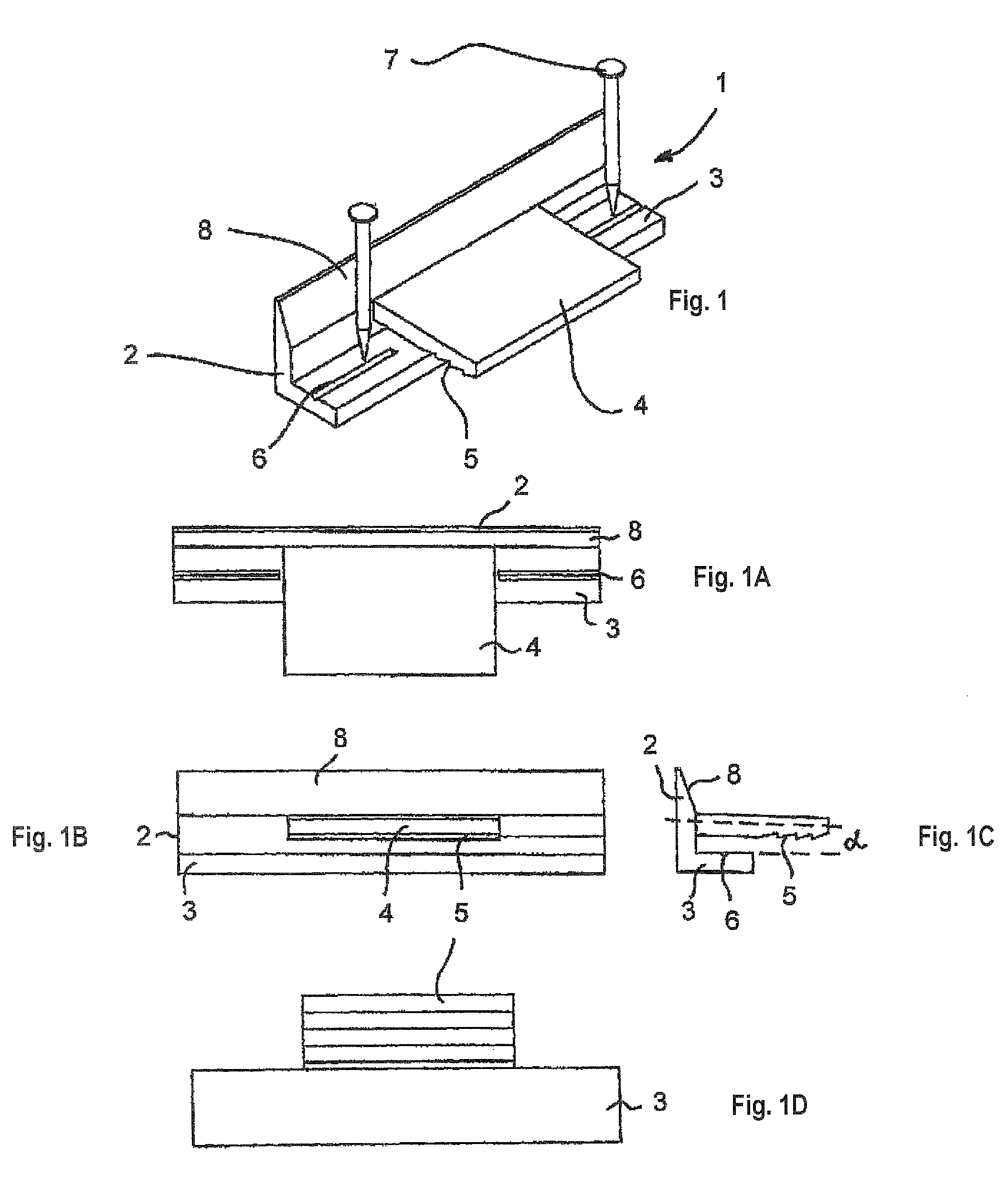
[0010]In order to give the fastening device a high stability, two factors should be considered. A first factor is to fasten the horizontal leg by means of a nail, a pin or a bolt as close as possible to the glass pane, i.e., the fastening element has to be driven or screwed in as close as possible to the glass pane. A second factor is to give the fastening portion a great length. However, when the fastening portion is designed too long, it would cover the horizontal leg so that there is no possibility to insert fixing elements from above. A nail can only be driven into the horizontal leg without restrictions, i.e. without spatial limitations as close as possible to the glass pane, when the fastening portion is shorter than the angular clamping piece itself. However, in the direction away from the glass pane, the fastening portion can be dimensioned relatively long and thus, the groove correspondingly deep so that the holding rail is fixed in a stable manner.
[0011]According to another feature of the invention, the fastening portion is slightly inclined towards the horizontal leg of the angular clamping piece. The fastening portion and the groove in the holding rail are dimensioned so that the fastening portion is slightly deflected upwardly when the holding rail is pushed onto it and is brought into a stressed state. Thus, the pre-stressed fastening portion acts through its bottom surface onto the holding rail and presses it to the frame reliably. By this advantageous further development of the invention, a still more reliable fixing of the holding rail is gained.
[0013]According to another feature of the invention, the lower surface of the fastening portion is provided with a holding profile which enables the holding rail to be pushed onto the fastening portion easily, but makes the removal therefrom difficult. Such profiles known as pine-cone or saw-tooth profiles act on the barb principle thereby further enhancing a fastening of the holding rail.
[0015]According to another feature of the invention, the angular clamping piece is made of a resilient plastic material which has a relatively great strength and can be punched by nails without causing problems.

Problems solved by technology

Moreover, mounting of ledges is relatively costly.
In practice, another problem is to hold a glass pane in its position tightly and reliably, which can not be ensured satisfactorily by all of the solutions known up to know.

Method used


Image

  • Fastening device with improved fastening portion for securement of a glass pane or a plate in a frame
  • Fastening device with improved fastening portion for securement of a glass pane or a plate in a frame
  • Fastening device with improved fastening portion for securement of a glass pane or a plate in a frame

Examples


Embodiment Construction

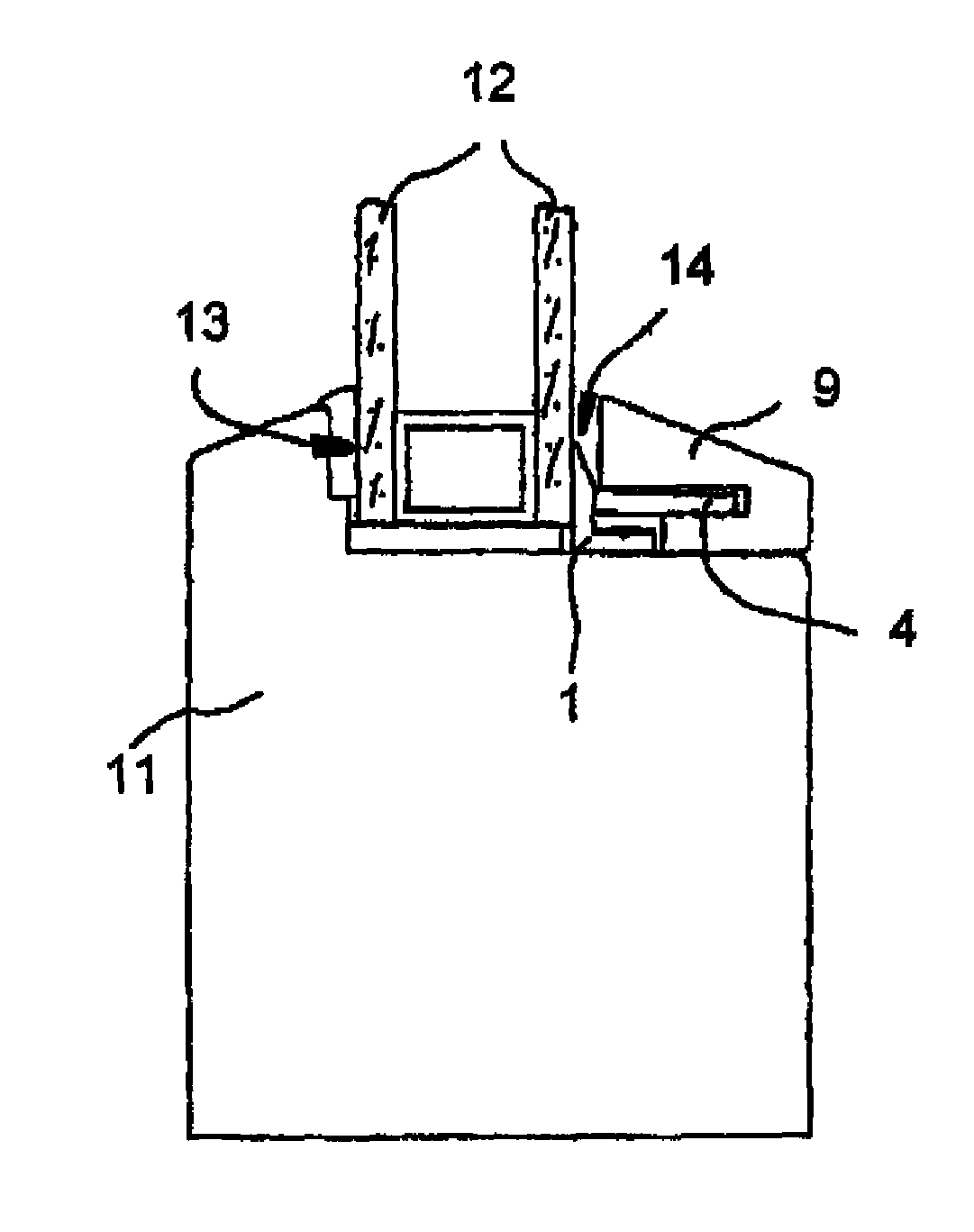
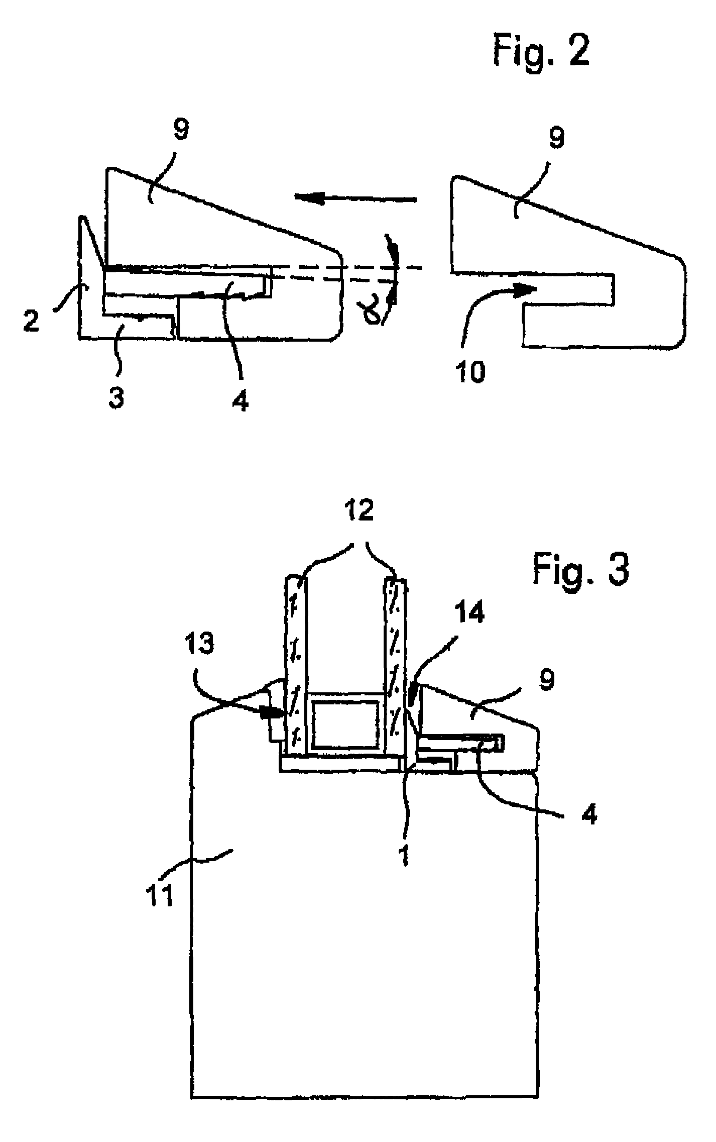
[0024]As recognizable from FIG. 1, the angular clamping piece 1 comprises a vertical leg 2 and a horizontal leg 3. A fastening portion 4 extends from the vertical leg 2, which has a predetermined distance to the horizontal leg 3 and is slightly inclined downwards it by a predetermined angle α. The lower surface of the fastening portion 4 is provided with a profile similar to that of a fir-cone.

[0025]As also recognizable from FIG. 1, the fastening portion 4 is shorter in length than the legs of the angular clamping piece 1. Those portions of the horizontal leg 3, which are not covered by the fastening portion 4, are provided with grooves 6 into which nails 7, for example, can be driven at a predetermined position. The vertical leg 2 comprises a taper cone 8, the meaning thereof being recognizable from FIG. 3.

[0026]Portions of the angular clamping piece, which are outlined in the top view, the side view, the front view and the bottom view and which correspond to those in the perspecti...


PUM


Abstract

The invention relates to a fastening means for preferably fastening a glass pane (12) in a frame structure made of wood or plastic material. The fastening means according to the invention is characterized by the following elements: several angular clamping pieces (1) and a holding rail (9), wherein each of the angular clamping pieces comprises two legs extending perpendicularly to each other and the vertical leg comprises a plate-like fastening portion (4), which extends from the center part thereof outwardly at a predetermined distance to the horizontal leg and is shorter than the angular clamping piece itself, wherein the holding rail (9) extending along the glass pane is provided in its longitudinal direction with a groove (10), the with thereof matching to the thickness of the fastening portion, and wherein, in the mounted state, the glass pane contacts at its backside the stop provided in the frame (11), several angular clamping pieces are tightly pressed to the front side of the glass pane and fixed by fixing elements (7), and the holding rail (9) is pressed onto the fastening portion (4) by its longitudinal groove (10).

Description

BACKGROUND OF THE INVENTION[0001]The present invention relates to a device for fastening glass panes, preferably, in a frame made of wood or plastic material. For fastening glass panes or plates in doors, glass cupboards etc., compound arrangements of ledges are used, such as described in the documents DE 195 25 206, DE 296 00 399 U1, DE 42 16 260 C2 and DE 199 55 639 A1.[0002]Frequently, it is desirable that such compound arrangements of ledges are easily releasable so that a broken glass pane can be exchanged very quickly, for example. This is ensured by a compound arrangement of ledges described in DE 296 00 399 U1, but conditionally only. FIG. 5 of this document shows an embodiment according to the prior art, which will be described in the following. A profiled ledge 6, 7 each is arranged on the edges of a recess in a door-plate 3, which are held together by a connecting element 1. A glass pane 2 is fitted between the ledges 6, 7 without any clearance. The connecting element 1 c...

Claims


Application Information

Patent Timeline
Patent Type & Authority Patents(United States)
IPC IPC(8): E06B3/54
CPCE06B3/5481E06B3/5828
Inventor KNAPP, FRIEDRICH
Owner KNAPP FRIEDRICH
Learn More