Forced balanced system

a stabilizer and balanced technology, applied in the direction of drilling pipes, directional drilling, borehole/well accessories, etc., can solve the problems of reducing the effective diameter of the stabilizer, and being slightly under gauge and not automatically adjustable. , to achieve the effect of valuing the rig tim

Active Publication Date: 2011-02-01
SCHLUMBERGER TECH CORP
View PDF35 Cites 12 Cited by
  • Summary
  • Abstract
  • Description
  • Claims
  • Application Information

AI Technical Summary

Benefits of technology

Exemplary embodiments of the present invention may advantageously provide several technical advantages. For example, exemplary embodiments of this invention provide an adjustable stabilizer that is automatically and continuously adjustable during use. As such, the invention is suitable for use in boreholes that rapidly change size and shape. Moreover, the inventive stabilizer operates without any resetting from the surface or stoppage in drilling. Thus, valuable rig time tends to be preserved.

Problems solved by technology

Commonly utilized near-bit stabilizers are typically slightly under gauge and not automatically adjustable.
These difficulties become more significant in oversize boreholes (e.g., due to washout of a soft formation) and upon stabilizer wear (which decreases the effective diameter of the stabilizer).
Large radial vibrations and shock loads are known to occur within this freedom movement.
Steering difficulties are also encountered as the near-bit stabilizer no longer pivots predictably.
While rotary steerable tools are known to provide excellent steerability in certain drilling conditions and automatically adjustable stabilization, they are not suitable for many downhole applications (owing in part to the high cost of such tool deployments).
While adjustable, rotationally fixed stabilizers are known, for example, as described above, they do not provide for automatic adjustment to the borehole diameter.

Method used


Image

  • Forced balanced system
  • Forced balanced system
  • Forced balanced system

Examples


Embodiment Construction

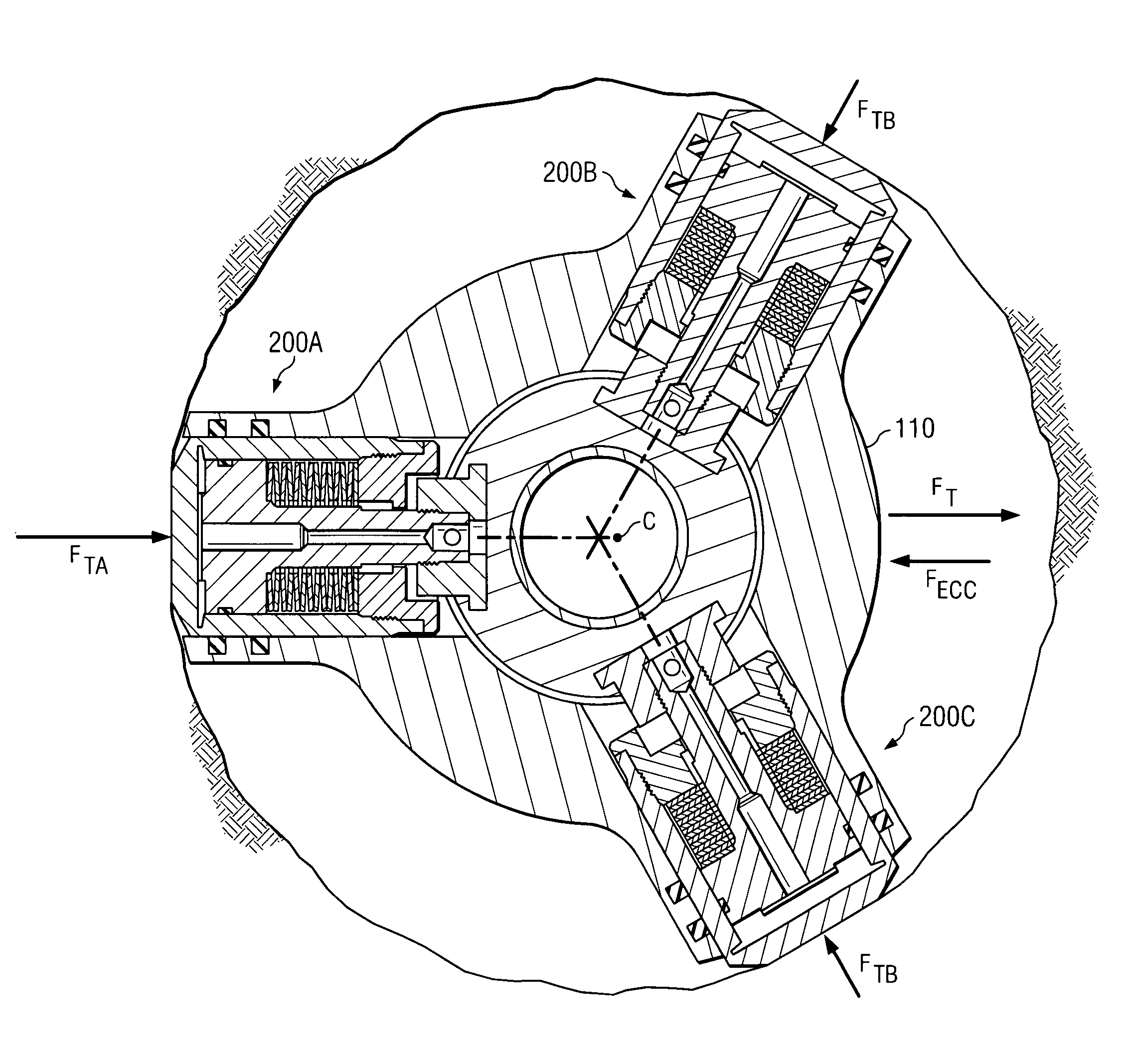
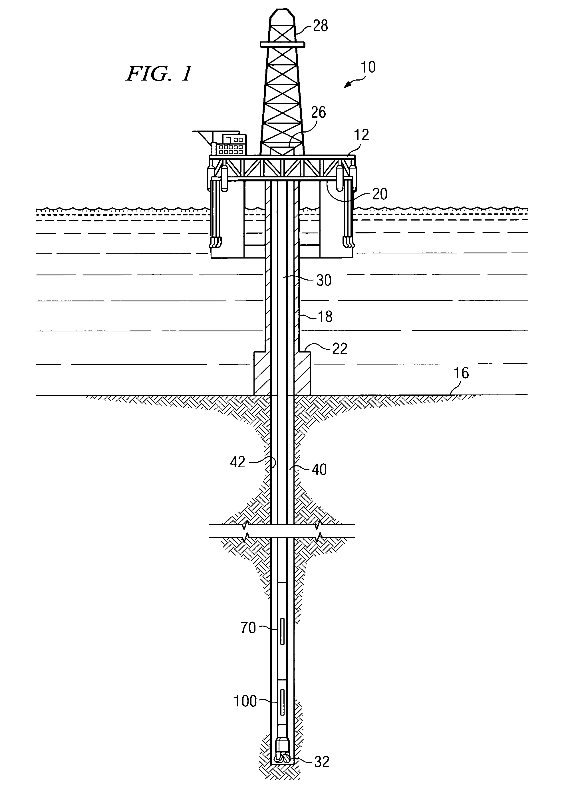
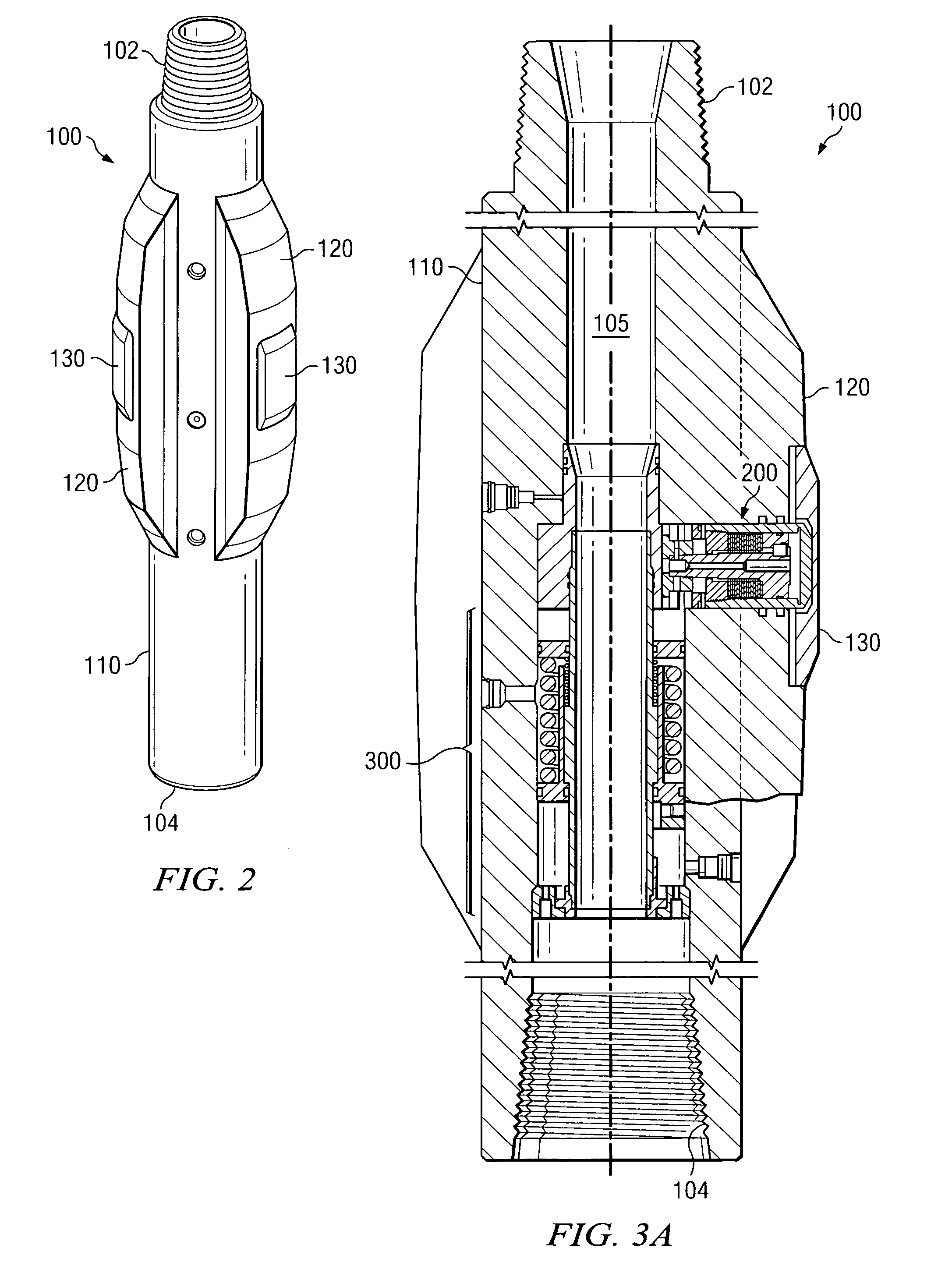
Referring first to FIGS. 1 through 10B, it will be understood that features or aspects of the embodiments illustrated may be shown from various views. Where such features or aspects are common to particular views, they are labeled using the same reference numeral. Thus, a feature or aspect labeled with a particular reference numeral on one view in FIGS. 1 through 10B may be described herein with respect to that reference numeral shown on other views.

FIG. 1 illustrates a drilling rig 10 suitable for utilizing exemplary stabilizer and hydraulic control system deployments of the present invention. In the exemplary embodiment shown on FIG. 1, a semisubmersible drilling platform 12 is positioned over an oil or gas formation (not shown) disposed below the sea floor 16. A subsea conduit 18 extends from deck 20 of platform 12 to a wellhead installation 22. The platform may include a derrick 26 and a hoisting apparatus 28 for raising and lowering the drill string 30, which, as shown, extends...


PUM


Abstract

A downhole tool including a purely mechanical stabilizer is disclosed. The stabilizer includes a plurality of fixed blades, each of which includes at least one automatically extendable and retractable piston. In use, a balance of forces determines the radial position of each piston; a hydraulic force urging the piston outward, a spring force urging the piston inward, and external forces acting on the tool (e.g., the force of the borehole wall urging the pistons inward). The stabilizer is further configured such that a balance of forces between the pistons causes the tool to be advantageously automatically and continuously centered during rotation of the tool in the borehole. As such, the invention is suitable for use in boreholes that rapidly change size and shape.

Description

RELATED APPLICATIONSNone.FIELD OF THE INVENTIONThe present invention relates generally to a downhole stabilizer, for example, including a near-bit stabilizer. More particularly, embodiments of this invention relate to a purely mechanical stabilizer including a plurality of force-balanced pistons disposed to continually center the stabilizer in a borehole during rotation therein.BACKGROUND OF THE INVENTIONNear-bit stabilizers are well known in downhole drilling applications and are commonly utilized in conjunction with rotary steerable systems in directional drilling applications. Commonly utilized near-bit stabilizers are typically slightly under gauge and not automatically adjustable. As a result, the stabilizer is offset from the center of the borehole by half the difference between the borehole diameter and the outside diameter of the stabilizer. The direction of offset is variable and generally cannot be predicted. Moreover, the stabilizer is typically free to move and vibrate i...

Claims


Application Information

Patent Timeline
Patent Type & Authority Patents(United States)
IPC IPC(8): E21B7/00
CPCE21B17/1014
Inventor EPPINK, JAY MILTON
Owner SCHLUMBERGER TECH CORP
Why Eureka
Try Eureka