Pre-installed anti-rotation key for threaded connectors

a technology of anti-rotation and threaded connectors, which is applied in the direction of screw threaded joints, drilling pipes, mechanical equipment, etc., can solve the problems of consuming valuable rig time and requiring complex tools, and achieve the effect of prolonging rig tim

Active Publication Date: 2020-03-24
VETCO GRAY
View PDF9 Cites 1 Cited by
  • Summary
  • Abstract
  • Description
  • Claims
  • Application Information

AI Technical Summary

Benefits of technology

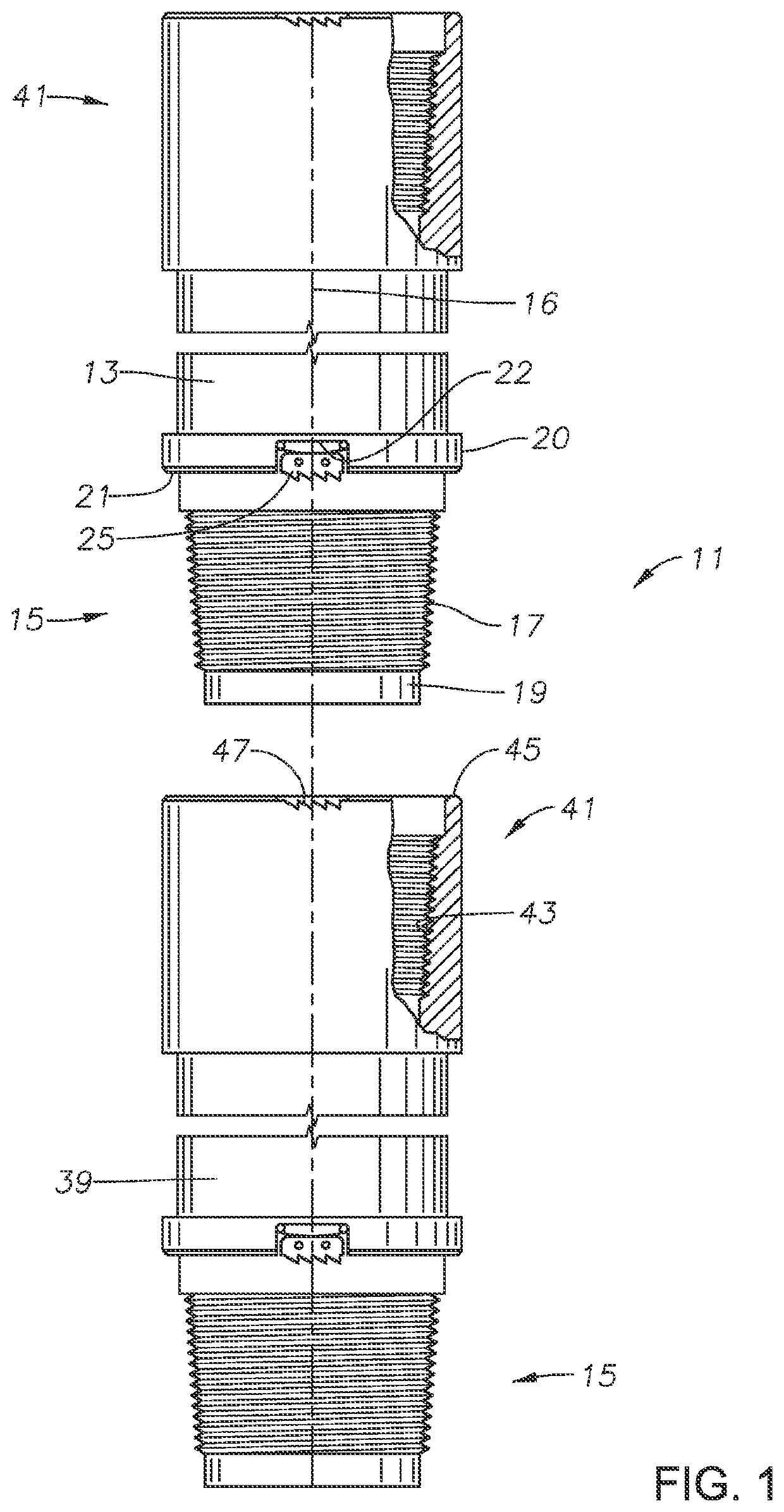
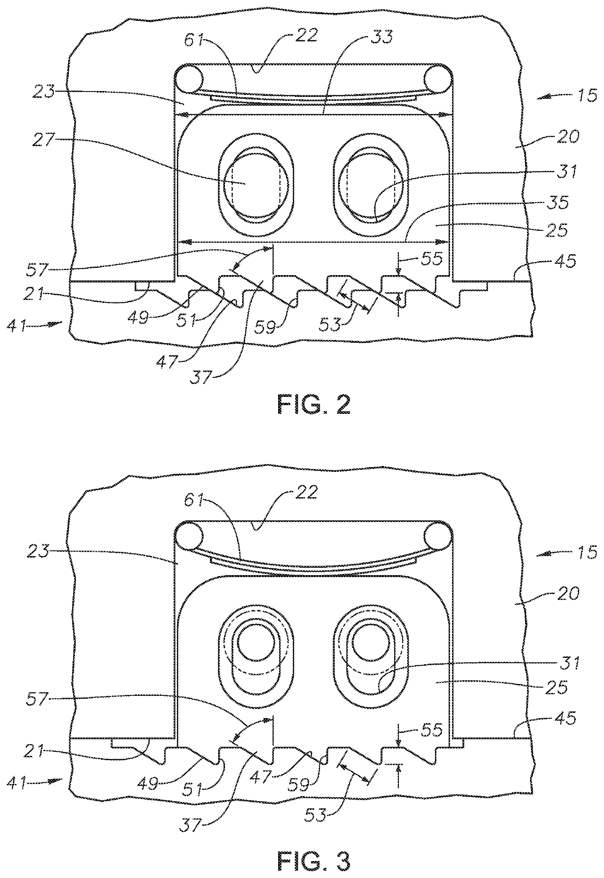
[0007]Systems and methods disclosed herein provide an anti-rotation device for threaded connections having a pre-installed anti-rotation key. The anti-rotation key can be installed by the manufacturer with no adjustments required in the field. A recess in one of the pins or boxes allows the anti-rotation key to ratchet along grooves of the other of the pin or box as the connection is rotated in a make-up direction. A biasing member urges the anti-rotation key into the grooves to provide resistance when rotating the connection in an unscrewing direction. Embodiments disclosed herein eliminate the need for installation tools on site and for extended rig time because the anti-rotation key is pre-installed.
[0008]Systems and methods disclosed herein provide an anti-rotation key that produces significantly less axial load than some current anti-rotation devices. Due to not knowing where the shoulders of the pin and box would end up circumferentially relative to one another after make-up, some previous anti-rotation keys were designed to bite into the end of the box during installation and operational loading. The residual axial force left by these keys is quite high. Installing a key that must bite into the box also takes up valuable rig time and requires complex tools. Embodiments of the anti-rotation key disclosed herein, instead transfers load in predominantly the circumferential direction. Systems and methods disclosed herein provide an anti-rotation key that is installed into a clocked recess, that ensures that the anti-rotation key is properly aligned with the grooves when the pin and box are made-up, negating the need for time consuming installation on the rig.

Problems solved by technology

Due to not knowing where the shoulders of the pin and box would end up circumferentially relative to one another after make-up, some previous anti-rotation keys were designed to bite into the end of the box during installation and operational loading.
Installing a key that must bite into the box also takes up valuable rig time and requires complex tools.

Method used


Image

  • Pre-installed anti-rotation key for threaded connectors
  • Pre-installed anti-rotation key for threaded connectors

Examples


Embodiment Construction

[0016]The method and system of the present disclosure will now be described more fully hereinafter with reference to the accompanying drawings in which embodiments are shown. The method and system of the present disclosure may be in many different forms and should not be construed as limited to the illustrated embodiments set forth herein; rather, these embodiments are provided so that this disclosure will be thorough and complete, and will fully convey its scope to those skilled in the art. Like numbers refer to like elements throughout.

[0017]It is to be further understood that the scope of the present disclosure is not limited to the exact details of construction, operation, exact materials, or embodiments shown and described, as modifications and equivalents will be apparent to one skilled in the art. In the drawings and specification, there have been disclosed illustrative embodiments and, although specific terms are employed, they are used in a generic and descriptive sense onl...


PUM


Abstract

A tubular member connection system includes a pin having a central axis, external pin threads, and an annular pin lip at a shoulder surface. A box has internal box threads and an annular box lip at an end surface of the box. The box threads are shaped to mate with the pin threads to releasably secure the pin to the box. A recess is formed in an outer diameter surface of the pin and extends in an axial direction from the pin lip. An anti-rotation key is located within the recess and has a row of teeth along an outer edge. A fastener retains the anti-rotation key in the recess. A circumferentially extending series of grooves on the box lip are sized to engage the teeth and resist a rotation of the pin relative to the box in an unscrewing direction when the pin is releasably secured to the box.

Description

BACKGROUND[0001]1. Field of the Disclosure[0002]This invention relates in general to threaded tubular connections, such as for large diameter pipes used in offshore hydrocarbon drilling and production operations, and particularly to a device to prevent rotation of tubular members after they are made up.[0003]2. Background of the Disclosure[0004]Hydrocarbon production wells can have several strings of casing of differing diameters cemented in the well. Each casing string can be made up of joints of pipe having threaded ends that are secured together. Some casing joints have external threads on their upper and lower ends. A casing collar with internal threads secures the threaded ends together. In larger casing diameters, a casing collar with internal threads may be affixed, such as by welding, to one end of each tubular member, the other end having external threads. The portion of the connector having internal threads is commonly known as a female connector or box. The portion of the...

Claims


Application Information

Patent Timeline
Patent Type & Authority Patents(United States)
IPC IPC(8): F16L15/06E21B17/043E21B17/08F16L15/08
CPCE21B17/043E21B17/08F16L15/06F16L15/08
Inventor MCGOWAN, DANIEL PAULPALLINI, JR., JOSEPH WILLIAMMARTINCHICH, DENNIS ROBERTZAC-WILLIAMS, ANDREW ANDORLOOSE-MITCHELL, WILLIAM ALEXANDER
Owner VETCO GRAY
Why Eureka
Try Eureka