
Wheel bearing device and its quality management method

a technology of bearing device and bearing bearing, which is applied in the direction of mechanical equipment, instruments, transportation and packaging, etc., can solve the problems of substantial labor and cost, inability to discern the date of manufacture and the place of manufacture of the bearing imprint, and difficulty in ensuring the quality of the bearing. achieve the effect of facilitating shipment control

Inactive Publication Date: 2011-02-01
NTN CORP
View PDF28 Cites 7 Cited by
  • Summary
  • Abstract
  • Description
  • Claims
  • Application Information

AI Technical Summary

Benefits of technology

[0019]Another object of the present invention is to provide a quality control method for the wheel support bearing, in which manufacturing history can be readily apprehended with no need to dismantle the bearing and which can cope quickly and properly with the regular servicing or the like.
[0113]In the present invention, the IC tag affixed to the wheel support bearing may have recorded therein, information on whereabouts of the wheel support bearing starting from shipment of the wheel support bearing to delivery thereof to a customer. This facilitates the shipment control, the distribution control, the customer control, the maintenance control and others.

Problems solved by technology

However, even though the IC tag is merely affixed, it is used only for the control of, for example, identification information, manufacturing information and distribution information and the status of actual use of the wheel support bearing device cannot be stored.
However, in any suggested examples of the sensor incorporated wheel support bearing devices, the current status is detected for use in various controls of an automotive vehicle and none of them has a function of storing a result of detection as a history.
However, indication of the manufacturer's serial number, the date of manufacture and the place of manufacture shown by the imprint on the wheel support bearing cannot be discernible unless the bearing is removed from a member that defines a bearing housing.
Because of this, disassembling and reassembling require a substantial amount of labor.
In general, however, the information such as, for example, the manufacturer's serial number is ascertained when and after the wheel support bearing has been removed, resulting in expenditure of a substantial labor and cost.
However, it often occurs that only with the above described information concerning the mechanical elemental components, a technical phenomenon occurring in the mechanical elemental component cannot be revealed.
By way of example, depending on the difference in processing condition employed in the manufacturing steps, a difference may occur in quality, and such difference resulting from the difference in processing condition may not be often recognized from a result of examination.
The wheel support bearing is made up of a plurality of elemental components and, even though the result of examination or the like of the wheel support bearing itself after the latter has been assembled is known, inconveniences resulting from the difference in quality of the individual elemental components cannot be identified.
In the case of the wheel support bearing, which is a mechanical elemental component having rolling elements, even the slightest difference in material and / or precision may result in a large difference in performance as the wheel support bearing and, therefore, the suggested conventional quality control method utilizing the IC tags can hardly work out satisfactorily.
Also, even in the process control, with the conventional control method, in which for each process step records are written down in a book and / or inputted in a terminal, recording and inputting require a substantial amount of labor and, therefore, it is difficult to record in details a number of pieces of information.
In particular, in the case of what has been assembled with a plurality of elemental components such as observed in the wheel support bearing and in which each of the elemental components is produced by lots for each process step after having passed through a process ranging from purchase of materials to a grinding step by way of a forging step and then a heat treatment step, the control in the manufacturing process of each of the elemental components is complicated and a substantial amount of labor is required in accomplishing manual recording of the information and inputting operation.
Because of this, it is difficult to meet with the demands for the detailed history information on the wheel support bearing and, also, the control requires a substantial amount of cost.
In view of the foregoing, the application of the IC tags has been contemplated, but the control such as used in connection with automotive vehicles themselves cannot be applied to the wheel support bearings.
However, in the case of the wheel support bearing, which is a rolling bearing, since there is no elemental component which is complete and criterial such as the frame or the like in the automotive vehicle and, in the manufacturing process, each elemental component is manufactured through the forging and heat treatment steps, it is difficult to secure the IC tag to the wheel support bearing.
Also, in the case of the wheel support bearing, which is a rolling bearing, since the inner race, outer race, rolling elements, the hub and so on are individually controlled at each stage of the manufacturing process including purchase of materials, the forging step, the heat treatment step, the grinding step and son on, the application of the IC tag to the quality control poses a problem of how it should specifically be used and, therefore, the efficient application of the IC tag is difficult to achieve.

Method used


Image

  • Wheel bearing device and its quality management method
  • Wheel bearing device and its quality management method
  • Wheel bearing device and its quality management method

Examples


first embodiment

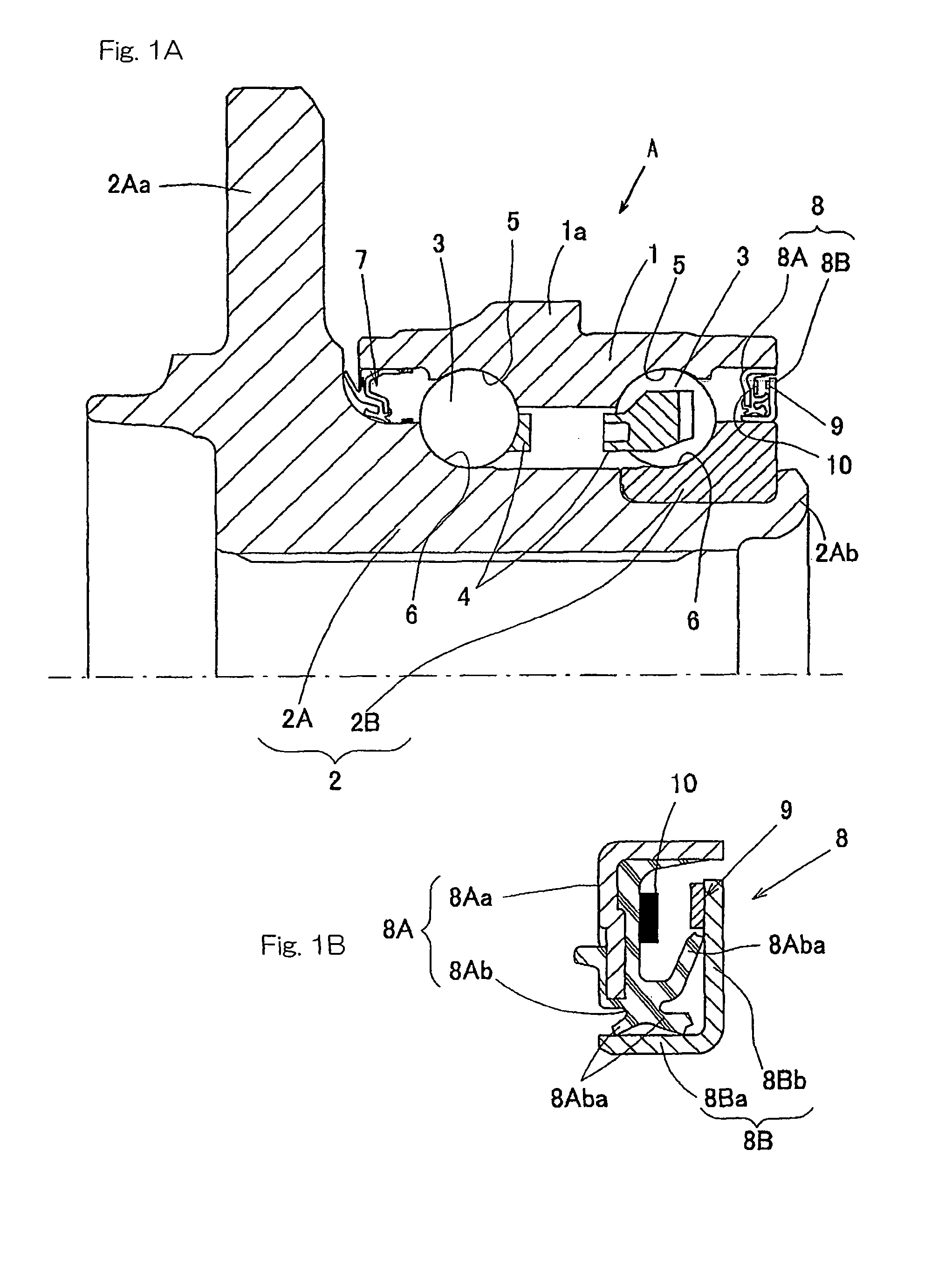
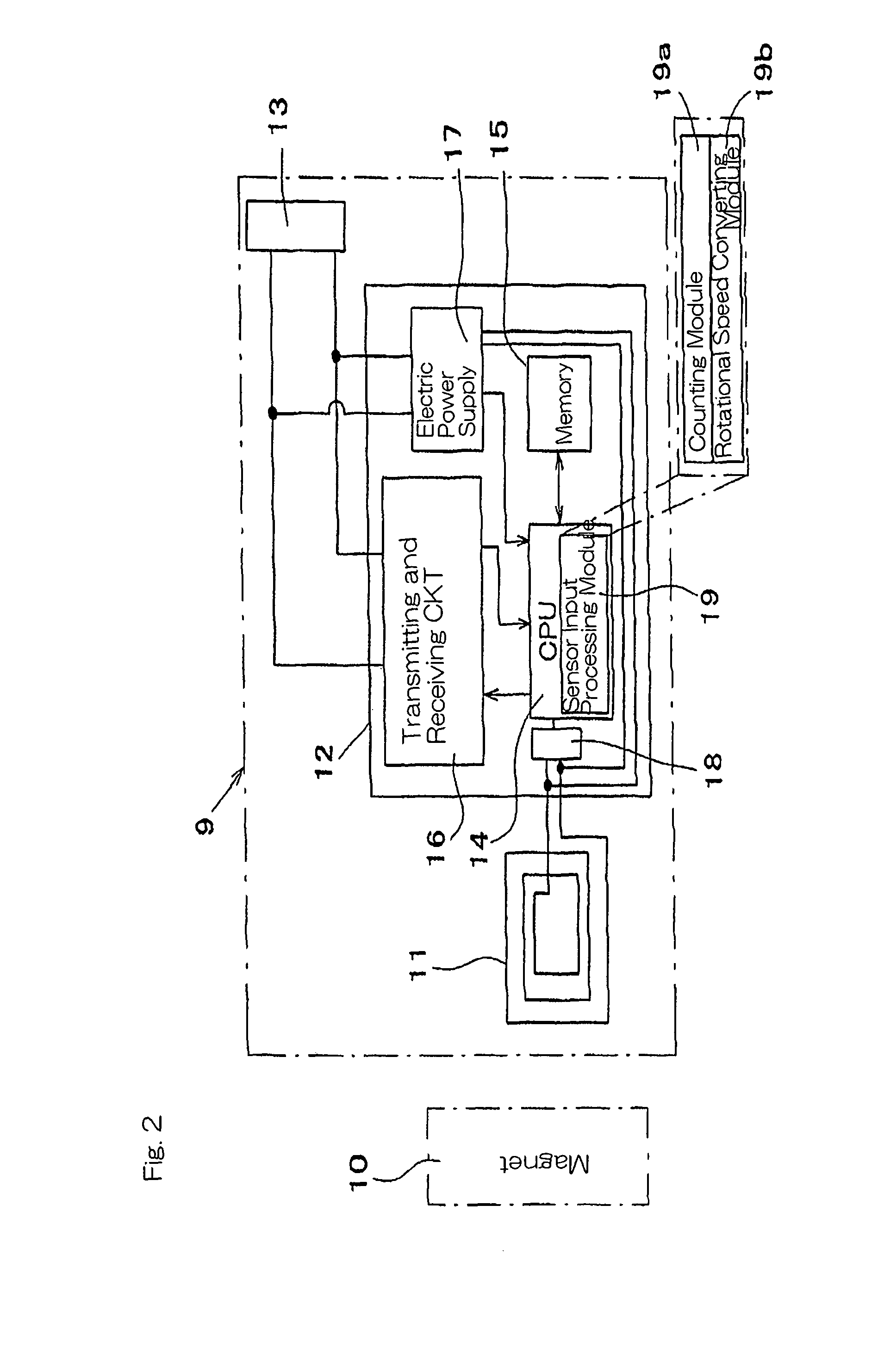
[0165]In this first embodiment, since the sensor 11 is the coil, an electromotive forge generates in the sensor 11 when rotated. This electromotive force can be utilized for driving the IC tag 9 and, also, by the effect of an electromotive force generated each time it move past the magnet 10, the rotation of the wheel support bearing device can be detected. A signal generated from the sensor 11 when the magnet 10 moves is counted by the counting module 19a and is then recorded in the memory 15. Also, the rotational speed converting module 19b records strongness and weakness of the magnetic field resulting from passage of the magnet 10 and then convert into a rotational speed. In this way, it is possible to record a history of rotational speeds.

[0166]The IC tag 9 is, in this first embodiment, fitted to the seal 8, and since the seal 8 is held at a position exposed to the outside of the wheel support bearing device, a contactless communication with the IC tag 9 is easy to achieve. Als...

fourth embodiment

[0173]In the case of this fourth embodiment, since the temperature sensor incorporated IC tag 9A is provided, a history of temperature inside the bearing or the like can be recorded.

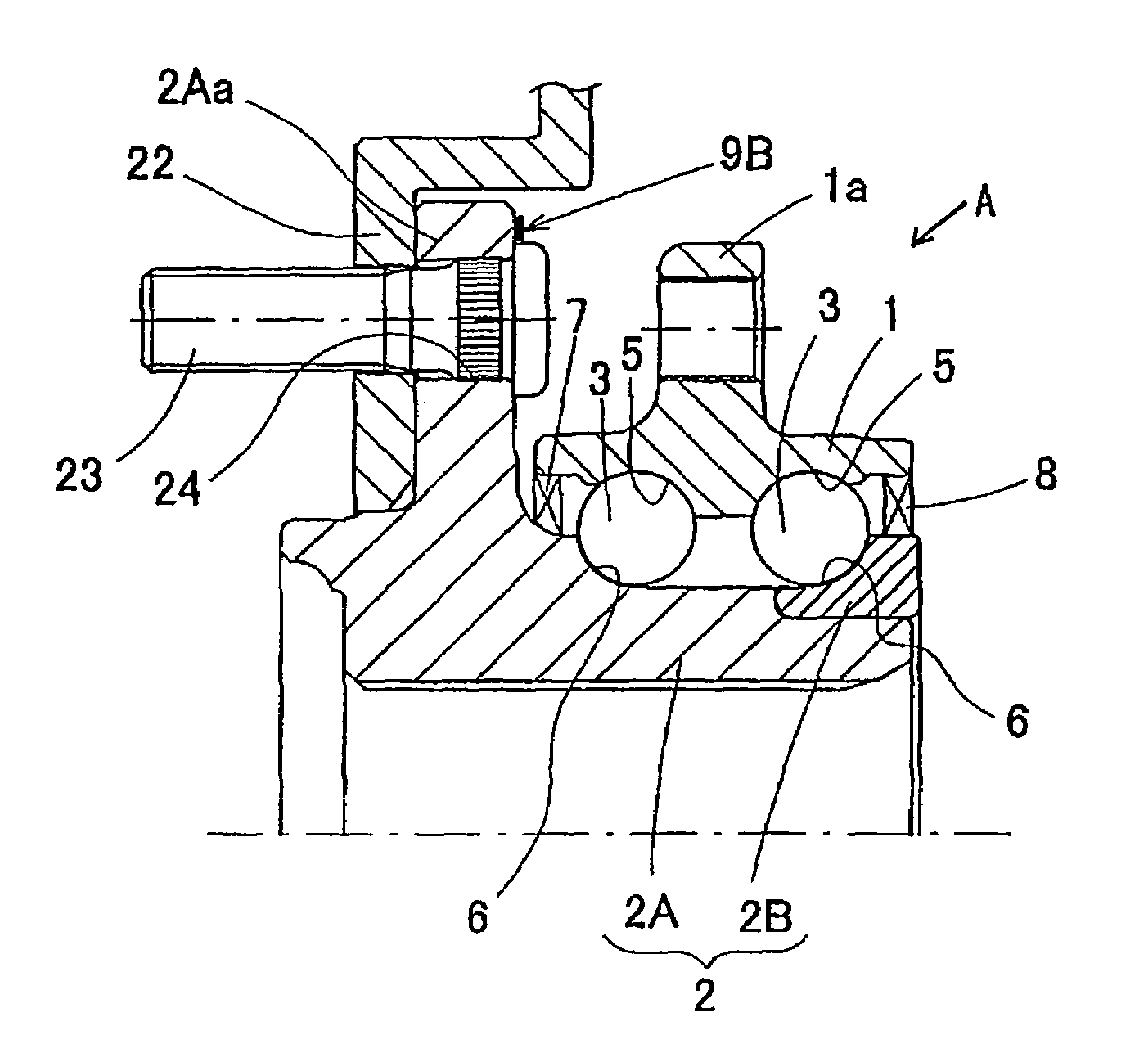
[0174]FIGS. 8 and 9 illustrate a fifth preferred embodiment of the present invention. This fifth embodiment is such that in the embodiment shown in FIGS. 6 and 7, in place of the IC tag 9A having the temperature sensor 11A incorporated therein, an IC tag 9B having a strain sensor 11B incorporated therein is employed. The strain sensor incorporated IC tag 9B is fitted to a root portion of the flange 2Aa of the hub 2A. The strain sensor 11B incorporated IC tag 9B is such that in the temperature sensor incorporated IC tag 9A shown in FIG. 7, in place of the temperature sensor 11A, the strain sensor 11B is provided as shown in FIG. 9. Other structural features of this fifth embodiment are similar to those shown and described in connection with the fourth embodiment with reference to FIGS. 6 and 7.

[0175]That ...

fifth embodiment

[0177]The hub 2A has a brake rotor 22 fitted thereto together with the wheel (not shown) by means of wheel mounting bolts 23. The bolts 23 are those press-fitted into corresponding press-fit holes 24 extending completely through the flange 2Aa. The brake rotor 22 may be either a brake disc or a brake drum. Other structural features of this embodiment are similar to those shown and described in connection with the fifth embodiment with reference to FIGS. 8 and 9.


PUM


Abstract

To provide a wheel support bearing device, in which the status of actual use is detected and stored as a history, an IC tag (9) capable of a contactless communication is affixed to the wheel support bearing device. This IC tag (9) is rendered to be a sensor incorporated IC tag integrated with or electrically connected with a sensor for detecting an object to be detected of the wheel support bearing device and a detection of the sensor is inputted through an input channel separate from a channel for the contactless communication. The sensor referred to above may be, for example, a coil and a magnet (10) capable of passing in the vicinity of the sensor incorporated IC tag (9) by the effect of a relative rotation.

Description

BACKGROUND OF THE INVENTION[0001]The present invention relates to a wheel support bearing device equipped with an IC tag and a sensor and a method of controlling the quality of the wheel support bearing for enabling a control thereof with the use of the IC tag to facilitate the traceability and to ease a response to the regular servicing.[0002]The IC tag adopting the RFID (Radio Frequency Identification) capable of contactless communication is being compactized and comes to be largely employed in the distribution of articles. Also, in recent years, demands for the traceability, that is, demands for the capability of pursuing the history, applicability and / or whereabouts of an object of interest are increasing, and the system has been suggested, in which ID codes and / or information associated therewith are stored in IC tags affixed to various machine component parts such as, for example, gears so that they can be managed. (See, for example, the Japanese Laid-open Patent Publication N...

Claims


Application Information

Patent Timeline
Patent Type & Authority Patents(United States)
IPC IPC(8): G06K21/00
CPCB60B27/00F16C33/78F16C41/007F16C41/008G01M13/04F16C2326/02F16C19/185F16C19/186
Inventor MURANAKA, MASAHIROITAKURA, HIROAKIMORITA, SHINJIKUCHIKI, YOSHIAKI
Owner NTN CORP
Learn More