Constant velocity universal joint and quality control method for the same

a constant velocity universal joint and quality control technology, applied in the field can solve the problems of increasing the cost inability to confirm the actual use of constant velocity universal joints in a particular status, and inability to achieve standard ic tags to achieve satisfactory information recording, etc., to achieve the effect of facilitating control, custom control and/or maintenance control

Inactive Publication Date: 2011-07-12
NTN CORP
View PDF28 Cites 6 Cited by
  • Summary
  • Abstract
  • Description
  • Claims
  • Application Information

AI Technical Summary

Benefits of technology

[0019]A second object of the present invention is to provide a quality control method for the constant velocity universal joint, in which the information can be readily obtained with no need to dismantle the bearing and which can cope quickly and properly with the regular servicing or the like.
[0110]In the present invention, the IC tag attached to the constant velocity universal joint may be recorded with information concerning whereabouts of the constant velocity universal joint from shipment of the constant velocity universal joint to delivery thereof to a customer. In this way, the shipment control, the distribution control, the custom control and / or the maintenance control can be facilitated.

Problems solved by technology

The standard IC tags are often incapable of accomplishing a satisfactory information recording, when they are arranged on metals, due to radio wave absorption and radio wave reflection.
If the IC tags of a special construction capable of being arranged on metals are used, they will become expensive, which lead to increase of the cost of the constant velocity universal joints.
However, no clue is generally available, which is necessary to know how the constant velocity universal joint is used and, therefore, confirmation of the actual use thereof in a particular status is impossible to achieve.
Although an attempt is made to store and control the status-of-use of the automotive vehicle itself, it is not sufficient as information necessary to control the status-of-use of the constant velocity universal joint.
Also, in the event that the constant velocity universal joint is replaced with a fresh one in the automotive vehicle, it is not easy to know the status-of-use of the new constant velocity universal joint.
However, the indications such as the manufacturer's serial number, the date of manufacture and the place of manufacture, which are imprinted on the constant velocity universal joint, are not readily available unless the constant velocity universal joint is dismantled.
Because of this, disassembling and reassembling require a substantial amount of labors.
In general, the constant velocity universal joint must be removed to enable the information such as the manufacturer's serial number to be confirmed and this is indeed laborious and costly.
However, it may often occur that with those information on the mechanical elements, a cause of a trouble occurring in some of the mechanical elements cannot be clarified.
By way of example, the difference in quality may arise even due to the difference in processing conditions at each of the process steps, and such difference in processing condition cannot be recognized from a result of examination.
Since in the constant velocity universal joint, even the slight difference in material and precision brings about a substantial difference in performance, the hitherto suggested example of the quality control method utilizing the IC tags is incapable of resolving the problem.
Also, in the case of the control of the process steps, the conventional control method, in which for each process step, records are manually written in a book and / or inputted in a terminal, requires a substantial amount of labor and, therefore, it is indeed difficult to record a large amount of information in detail meticulously.
In particular, when it comes to mechanical products, for example, constant velocity universal joints, each of which is made up of a plurality of elements produced in lots in all stages of the manufacturing process including a step of material purchase, a grinding step, a forging step and then a heat treatment step, the control of each element in each step of the manufacturing process is complicated and a substantial amount of labor is required in accomplishing manual recording of the information and inputting operation.
Because of this, it is difficult to meet with the demands for the detailed history information on the mechanical products and, also, the control requires a substantial amount of cost.
In view of the foregoing, the application of the IC tags to the constant velocity universal joint has been contemplated, but the control method such as used in connection with automotive vehicles cannot be applied to the constant velocity universal joints.
However, in the case of the constant velocity universal joint, since the constant velocity universal joint has no element, which provides a complete fiducial such as the frame or the like in the automotive vehicle and since in the manufacturing process each element is manufactured through, for example, the forging and heat treatment steps, it is difficult to secure the IC tag to the constant velocity universal joint.
Also, in the constant velocity universal joint, since the outer race, the inner race, the retainer and so on are individually controlled after the manufacturing process including the step of material purchase, the forging step, the heat treatment step, the grinding step and so on, the application of the IC tag to the quality control poses a problem of how it should specifically be used and, therefore, the efficient application of the IC tag is difficult to achieve.

Method used


Image

  • Constant velocity universal joint and quality control method for the same
  • Constant velocity universal joint and quality control method for the same
  • Constant velocity universal joint and quality control method for the same

Examples


Embodiment Construction

[0144]Preferred embodiments of the present invention will now be described with particular reference to the accompanying drawings.

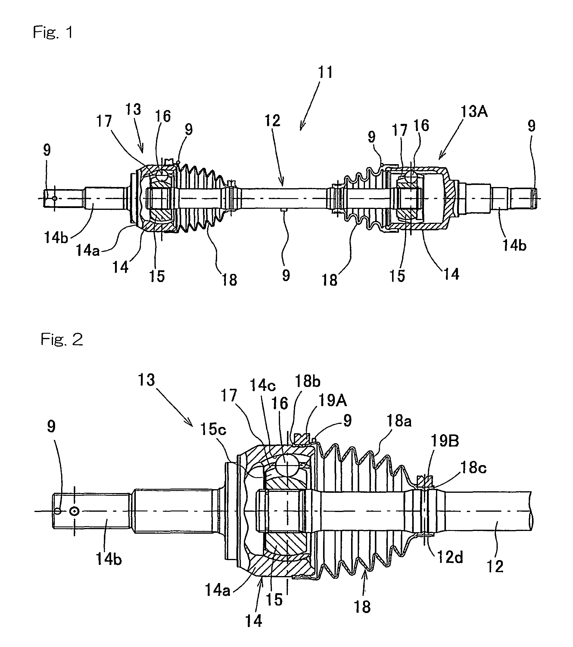
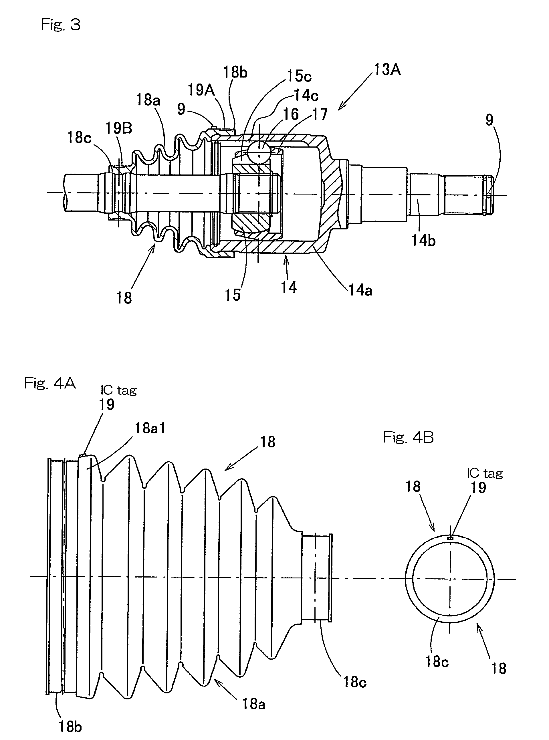
[0145]Specifically, FIG. 1 illustrates a vehicle drive shaft 11 having a pair of constant velocity universal joints mounted thereon, and FIGS. 2 and 3 illustrate those constant velocity universal joints on an enlarged scale, respectively. Referring to FIG. 1, the vehicle drive shaft 11 is made up of an intermediate shaft 12, a fixed type constant velocity universal joint 13 mounted on one of opposite ends of the intermediate shaft 12 and a sliding type constant velocity universal joint 13A mounted on the other of the opposite ends of the intermediate shaft 12. The fixed type constant velocity universal joint 13 is adapted to be drivingly coupled with a wheel support bearing assembly (not shown) of an automotive vehicle, whereas the sliding type constant velocity universal joint 13A is adapted to be drivingly coupled with a drive transmission system (not s...


PUM


Abstract

A quality control method for a constant velocity universal joint 13 includes a step of attaching an IC tag 9 to the constant velocity universal joint 13, a step of recording information in the IC tag 9 about the constant velocity universal joint 13, a utilizing step for reading the information recorded in the IC tag 9 at any arbitrarily chosen time. The IC tag 9 is attached to one of elements 2 such as an outer race 14, an inner race 15, an intermediate shaft 12 and boots 18, all forming respective parts of the constant velocity universal joint 13. This IC tag 9 is recorded with information on, for example, the manufacturing step, the identification number, the date of manufacture and / or the place of manufacture with respect to the elements 2 and the constant velocity universal joint 13.

Description

BACKGROUND OF THE INVENTION[0001]1. Field of the Invention[0002]The present invention relates to a constant velocity universal joint used in a car and an industrial machinery and a method of controlling the quality thereof with the use of an IC tag.[0003]2. Description of Prior Art[0004]In recent years, demands for the traceability of an object of interest, that is, demands for the capability of pursuing the history, application and / or whereabouts of an object of interest are increasing. In the quality control of mechanical products, for example, constant velocity universal joints, the quality of every steps (material purchase step, forging step, heat treatment step, grinding step and so on) of the manufacturing process ranging from material purchase to completion of manufacture and the manufacturing history of, for example, lots are desired to be confirmed on one-to-one basis or by unit of lots for each of the mechanical products.[0005]In automotive vehicles, since general mechanic...

Claims


Application Information

Patent Timeline
Patent Type & Authority Patents(United States)
IPC IPC(8): G06Q10/00G08B13/14F16D3/00B60Q1/00G06Q10/08
CPCF16C3/02F16C41/008F16D3/223G05B19/4183G06Q10/087F16D2250/00Y02P90/02
Inventor IKEDA, TAKESHIKONDOU, HIDEKI
Owner NTN CORP
Why Eureka
Try Eureka