Aircraft wing slat

a technology for aircraft wings and slats, applied in the field of aircraft wing slats, can solve the problems of saving valuable time and associated operating costs, and achieve the effect of reducing costs, cost and weight savings, and reducing efficiency

Active Publication Date: 2011-02-01
GKN AEROSPACE SERVICES LTD
View PDF33 Cites 10 Cited by
  • Summary
  • Abstract
  • Description
  • Claims
  • Application Information

AI Technical Summary

Benefits of technology

[0008]As the forward section of the wing slat is demountable from the main body section, if the forward section is damaged for any reason, such as an impact, then just this damaged forward section can be removed and replaced. This is a far simpler and quicker operation than removing the whole moveable wing slat, and subsequent refitting which requires time consuming realignment, saving valuable time and associated operating costs. Furthermore it is far less expensive to replace just a demountable forward section of a wing slat than the entire wing slat.
[0010]Providing an electrically powered heater in the forward section of the wing slat enables the wing slat to be protected against ice build up. When the ice protection system requires periodic maintenance, just the forward section of the wing slat may be removed and replaced rather than the entire moveable wing slat which requires precise re-alignment when being refitted so that the ice protection system may receive maintenance ‘off-site’ whilst the aircraft continues in service. Again, this reduces the time during which the aircraft is out of service reducing costs.
[0011]The provision of an electrically powered heater in the forward section of the wing slat to assist protection against ice build up enables the tubes for ducting of hot air in conventional wing slats to be omitted. This provides considerable cost and weight savings enabling the internal structure of the wing slat to be redesigned to provide the demountable forward section.
[0012]Furthermore, as the forward section of the wing slat is electrically heated, hot gasses do not need to be bled from the engines. Bleeding hot gasses from the engines reduces their efficiency, generally by several per cent.
[0013]The nose skin of the forward section of the wing slat preferably includes an integral heater. The mechanical properties of the heater and associated dielectric then contribute to the strength of the nose skin. This provides a stronger and lighter overall structure with enhanced thermal conductivity. The heater is preferably microporous to be integrated into the surrounding dielectric in the forward section of the wing slat.

Problems solved by technology

This is a far simpler and quicker operation than removing the whole moveable wing slat, and subsequent refitting which requires time consuming realignment, saving valuable time and associated operating costs.

Method used


Image

  • Aircraft wing slat
  • Aircraft wing slat
  • Aircraft wing slat

Examples


Embodiment Construction

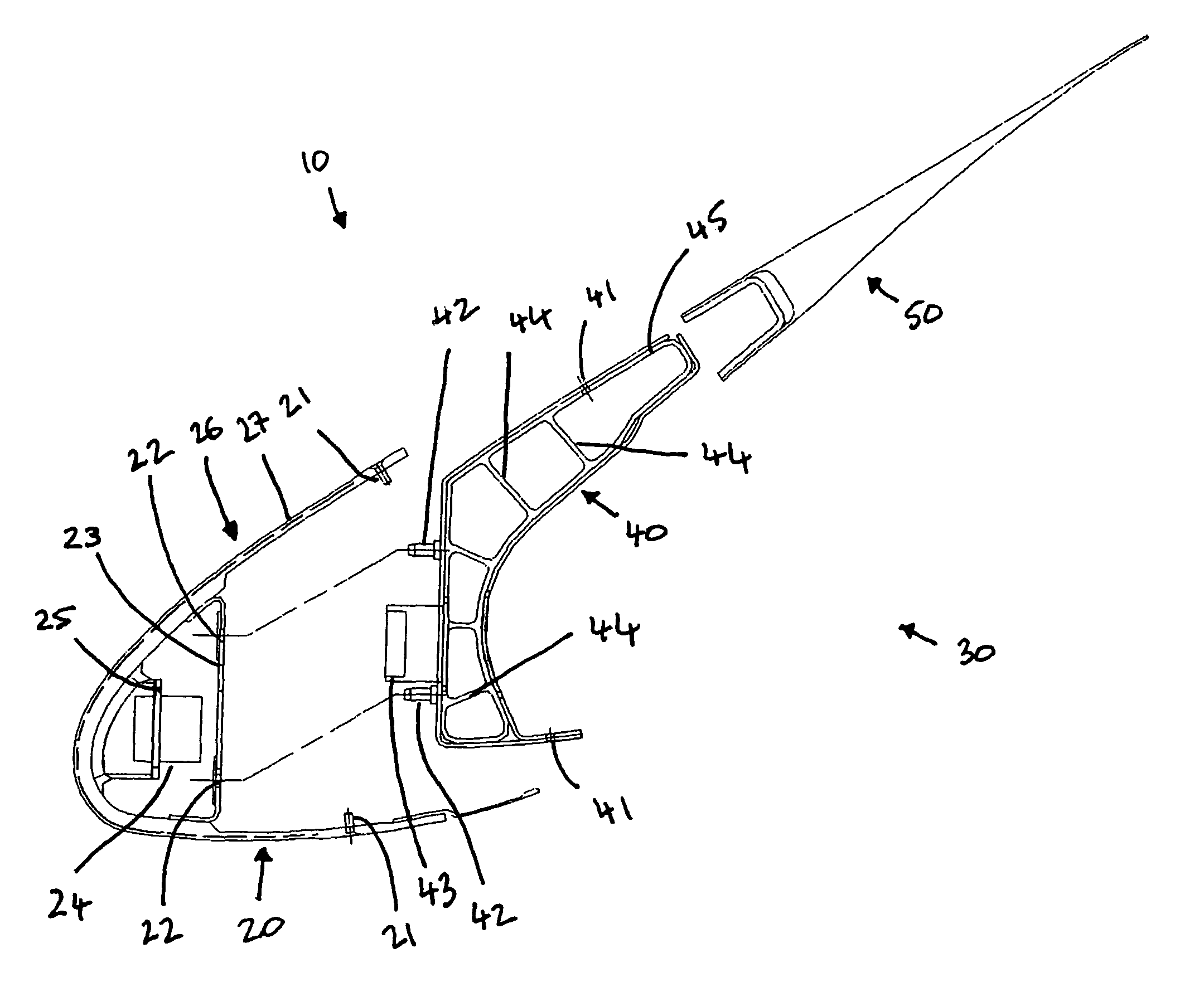
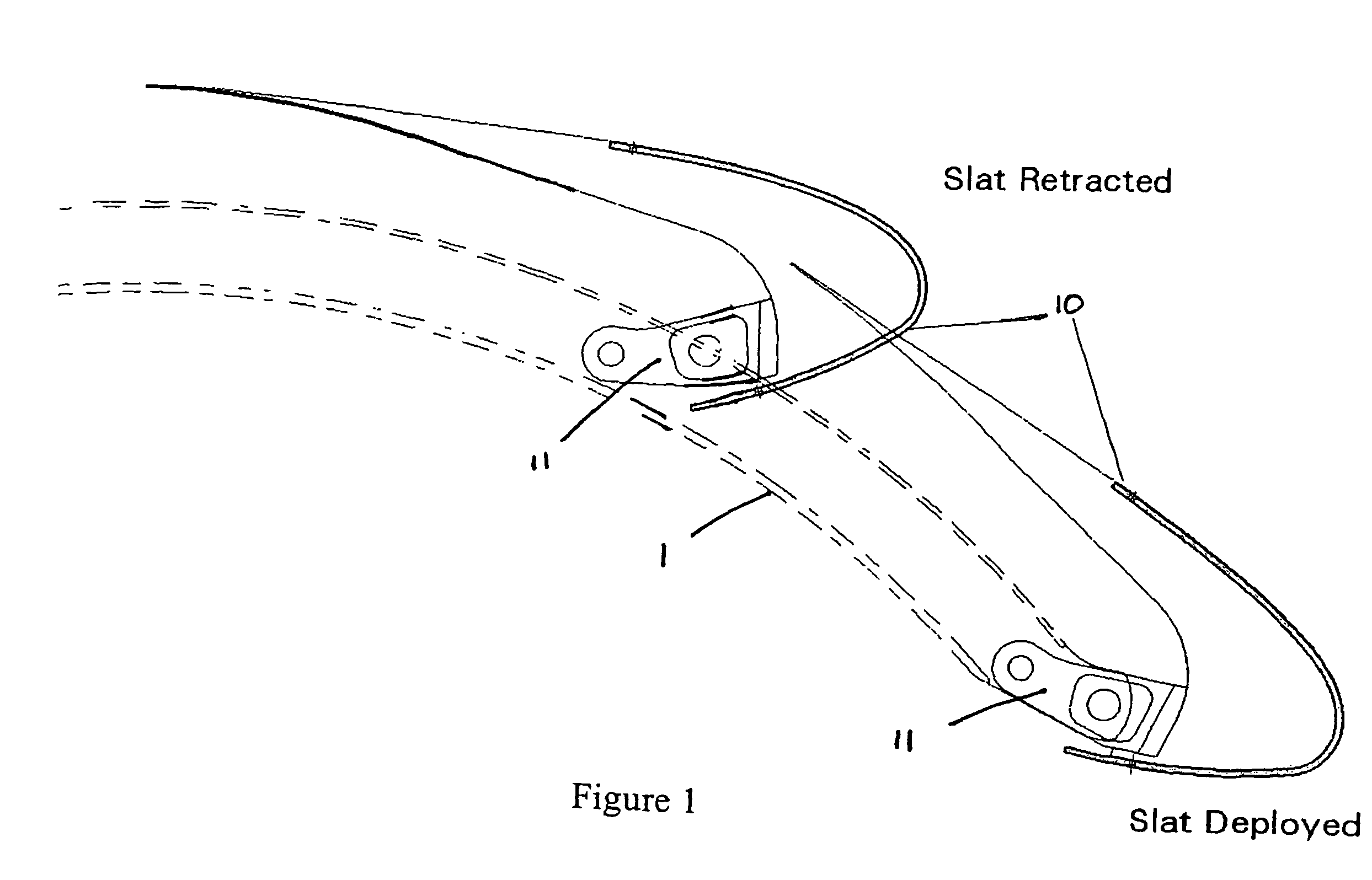
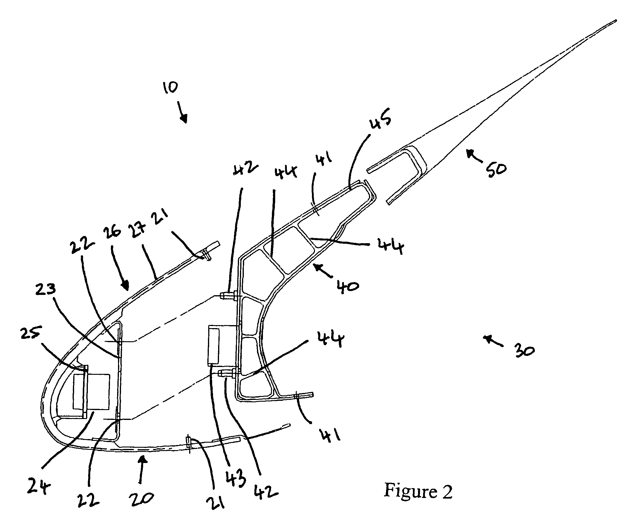
[0024]As shown in FIG. 1, a wing slat 10 is to be provided on a leading portion of an aircraft wing shown schematically by dotted lines 1. The wing slat 10 is provided on an articulated arm 11 to move it between deployed and retracted positions. The wing slat 10 comprises a forward section 20 and a main body section 30 as shown in FIG. 2. In this example the main body section 30 comprises a centre section 40 and an aft section or trailing edge wedge (TEW) 50. As shown in FIG. 2, the forward section 20 is demountable from or releasably secured to the main body section 30.

[0025]During use, the forward section 20 may be releasably secured to the centre section 40 of the main body section 30 by any suitable means. However, the forward section 20 is preferably secured to the centre section 40 by a securing means that enables the forward section 20 to be removed and replaced quickly and easily, such as the retaining screws 21 on the forward section 20 to be secured in corresponding holes ...


PUM


Abstract

An aircraft wing slat for mounting to a leading portion of an aircraft wing includes a main body section and a forward section, wherein the forward section is demountable from or releasably secured to the main body section. The forward section may have a nose skin with an electrically powered heater. The electrically powered heater may be integral with the nose skin and may be microporous such that it is integrated into surrounding dielectric to contribute to the mechanical strength of the nose skin. A demountable forward section of an aircraft wing slat, a main body section of an aircraft wing slat arranged to receive a demountable forward section, an aircraft wing and an aircraft wing slat with a nose skin with an electrically powered heater are also disclosed.

Description

CROSS-REFERENCE TO RELATED APPLICATIONS[0001]This application claims the benefit of U.S. Provisional Patent Application Ser. No. 60 / 711,954, filed Aug. 26, 2005, entitled AIRCRAFT WING SLAT, which application is incorporated by reference herein in its entirety, and claims priority to United Kingdom Patent Application No. 0517609.4, filed Aug. 25, 2005, entitled AIRCRAFT WING SLAT.FIELD OF THE INVENTION[0002]The present invention relates to an aircraft wing slat, in particular an aircraft wing slat for a leading portion of an aircraft wing.BACKGROUND OF THE INVENTION[0003]Wing slats are mounted to the leading portion of an aircraft wing and are moveable relative to the wing to manoeuvre the aircraft during flight.[0004]A wing slat is generally heated to reduce the build up of ice which could interfere with the operation of the wing slat to the detriment of the safety of the aircraft. Currently most civil aircraft wing slat designs use hot gas for ice protection purposes. Such technol...

Claims


Application Information

Patent Timeline
Patent Type & Authority Patents(United States)
IPC IPC(8): B64C3/50B64D15/12
CPCB64C9/22B64C9/24B64D15/12Y02T50/44Y02T50/40
Inventor ARMSTRONG, DAVID J.PRINGLE, GLEN R.BROWN, MAXWELL E.
Owner GKN AEROSPACE SERVICES LTD
Why Eureka
Try Eureka