
Bar coupling apparatus and methods

a technology of coupling apparatus and bar, which is applied in the direction of coupling, rod connection, manufacturing tools, etc., can solve the problems of relative inefficiency, deformation, and full strength of the bar, and achieve the effect of increasing the surface area of the bar in contact and more bonding

Active Publication Date: 2011-02-01
WEAVER INNOVATIONS
View PDF48 Cites 16 Cited by
  • Summary
  • Abstract
  • Description
  • Claims
  • Application Information

AI Technical Summary

Benefits of technology

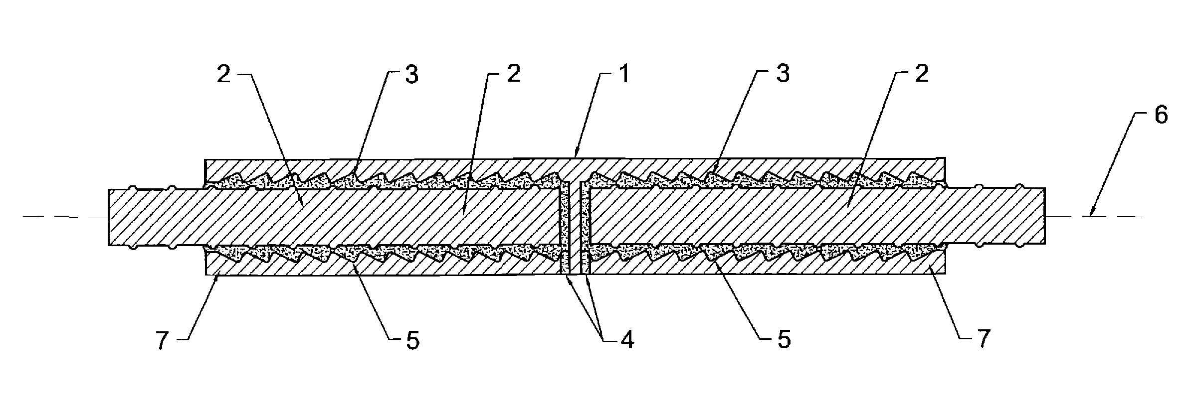
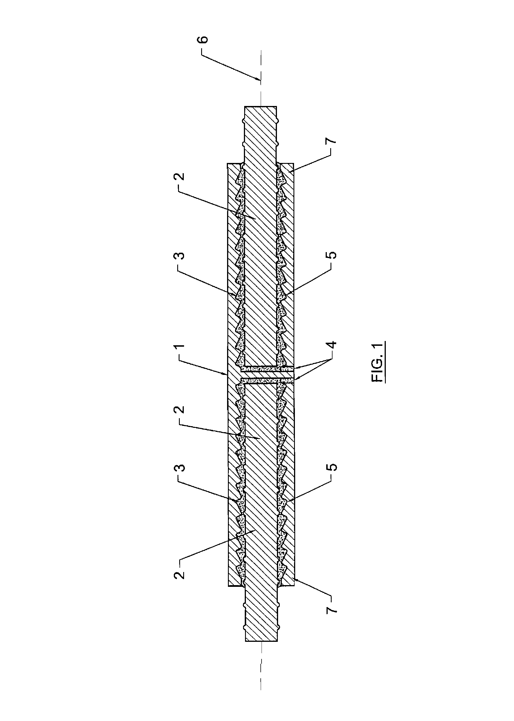
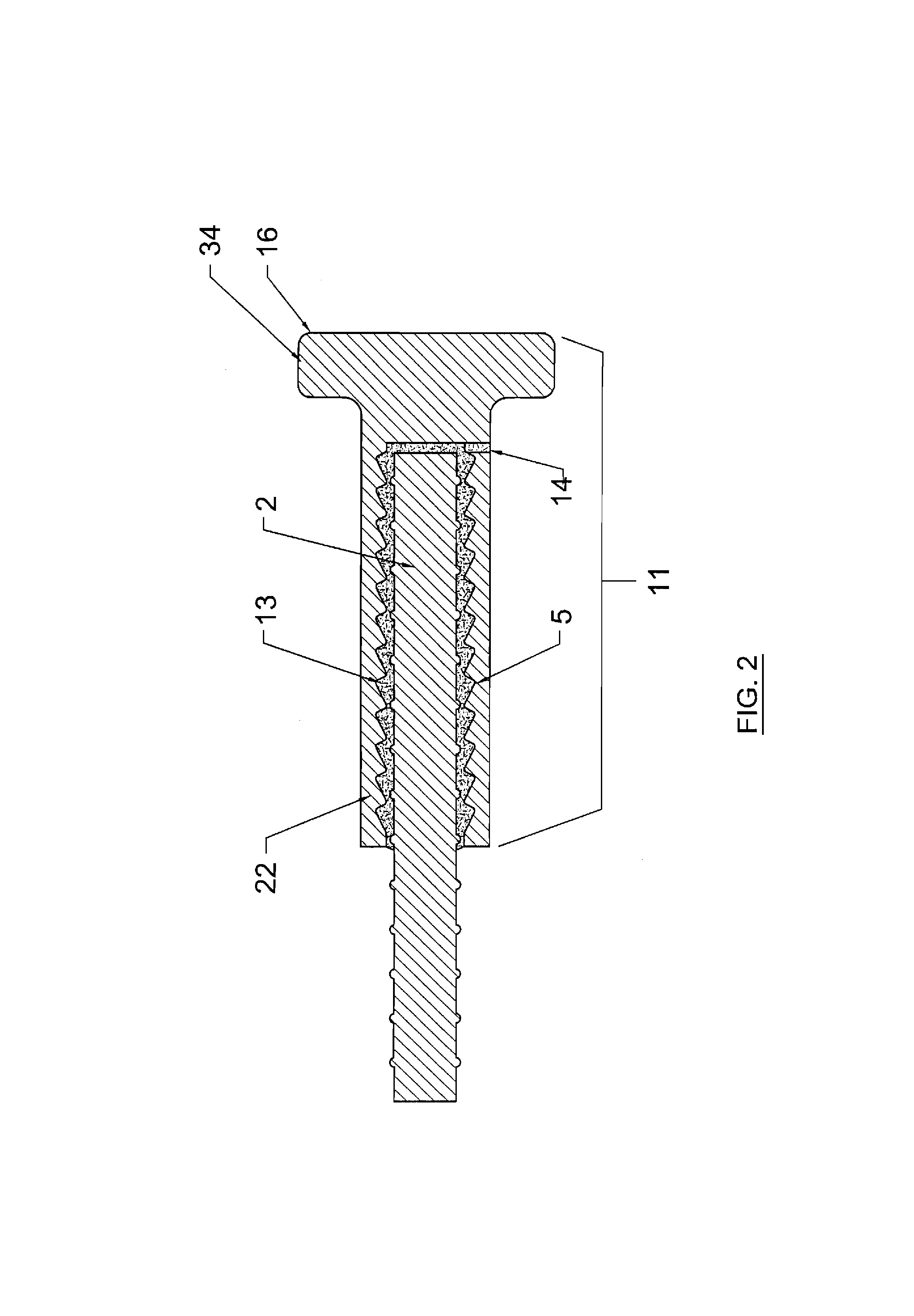
[0007]In embodiments with deformations of the inner surface of the contiguity, such deformations may serve several functions. First, the deformations (in particular their size relative to the reinforcing bar and the gap formed thereby) may be sized to provide passages through which the adhesive can flow to surround the entire reinforcing bar. Such, as an ancillary functionality, increases the surface area of the bar that is in contact with the adhesive, allowing more bonding between the adhesive and the reinforcing bar. Additionally, the deformations provide a mechanical anchorage for the adhesive. The deformations mechanically engage the adhesive to resist the tendency of the adhesive to be withdrawn from the device when a tension force is applied to the reinforcing bar. As should be understood, in particular embodiments of the inventive technology, deformations on the inner surface of the holes aid in force transfer through wedging action on the cured adhesive. It is also of note that no special tools are required for installation and that no special treatment of the deformed reinforcing bars is required for installation.

Problems solved by technology

Since the concrete is relatively inefficient in resisting or withstanding such stresses, reinforcing steel is added where these stresses occur in a structure to significantly increase the overall strength of the structure.
However, because forces are transferred from the reinforcing bar to the concrete primarily by the mechanical keying of the reinforcing bar deformations, a certain length of bar, and therefore a certain number of deformations, is required to develop the full strength of the bar.

Method used


Image

  • Bar coupling apparatus and methods
  • Bar coupling apparatus and methods
  • Bar coupling apparatus and methods

Examples


Embodiment Construction

[0019]As mentioned earlier, the present invention includes a variety of aspects, which may be combined in different ways. The following descriptions are provided to list elements and describe some of the embodiments of the present invention. These elements are listed with initial embodiments, however it should be understood that they may be combined in any manner and in any number to create additional embodiments. The variously described examples and preferred embodiments should not be construed to limit the present invention to only the explicitly described systems, techniques, and applications. Further, this description should be understood to support and encompass descriptions and claims of all the various embodiments, systems, techniques, methods, devices, and applications with any number of the disclosed elements, with each element alone, and also with any and all various permutations and combinations of all elements in this or any subsequent application.

[0020]At least one embo...


PUM


Abstract

Particular embodiments of the inventive technology relate to a device for connecting the ends of two concrete reinforcing bars in which a metal sleeve has chambers at each end to accommodate the end of one reinforcing bar. Forces may be transferred from one bar to the other through, the use of, inter alia, an adhesive established within the space between the outside of the reinforcing bars and the deformed inner surface of the sleeve. The chambers are, preferably, separated by a fluid impervious barrier. One port associated with each chamber may be established to allow fluid such as air to escape, preventing air voids in the adhesive. Another configuration of the inventive device would be intended for the retention (under load, of course) of only one reinforcing bar, with an enlarged flange for anchoring the end of one reinforcing bar, perhaps at and outer surface of, e.g., a concrete slab.

Description

CROSS REFERENCES TO RELATED APPLICATIONS[0001]This application is a continuation of prior International Patent Application Number PCT / US2009 / 031306, filed Jan. 16, 2009, said international application hereby incorporated herein in its entirety and itself claiming benefit of and priority to U.S. Provisional Patent Application No. 61 / 021,505, filed 16 Jan., 2008, said provisional application also incorporated herein in its entirety.BACKGROUND OF THE INVENTION[0002]Generally, the inventive technology relates to the field of bar retention. More specifically, the inventive technology, in embodiments, relates to bar coupling sleeve apparatus (e.g., rebar coupling sleeve apparatus), bar end portion retainer apparatus and bar retention methods that may find particular application in, e.g., the reinforced structure construction industry.BACKGROUND ART[0003]In reinforced concrete construction, including buildings, bridges, and other structures, reinforcing steel (e.g., rebar) is used to resis...

Claims


Application Information

Patent Timeline
Patent Type & Authority Patents(United States)
IPC IPC(8): E04C5/16
CPCE04C5/161E04C5/165Y10T403/5733Y10T403/473Y10T403/551
Inventor WEAVER, JASON M.
Owner WEAVER INNOVATIONS
Learn More